Multi-stage terminal outputs – Emerson 1F92 User Manual
Page 10
8
MULTI-STAGE TERMINAL OUTPUTS
MULTI-STAGE TERMINAL OUTPUTS
MULTI-STAGE TERMINAL OUTPUTS
MULTI-STAGE TERMINAL OUTPUTS
MULTI-STAGE TERMINAL OUTPUTS
Refer to equipment manufacturers’
instructions for specific system
wiring information.
You can configure the thermostat for
use with either multi-stage electric
heat systems or multi-stage gas
systems. When configured for
electric heat, the G terminal
(blower/fan) will be energized on a
call for heat.
This thermostat is designed to
operate a single-transformer system.
If you have a two-transformer
system, cut and tape off one
transformer. If transformer safety
circuits are in only one of the
systems, remove the transformer of
the system with NO safety circuits. If
required, replace remaining trans-
former with a 75VA Class II
transformer. After disconnecting one
transformer, the two commons must
be jumpered together.
Use the terminal output information
below to help you wire the thermo-
stat properly for your multi-stage
system. After wiring, see CON-
FIGURATION section for proper
thermostat configuration.
THERMOST
THERMOST
THERMOST
THERMOST
THERMOSTA
A
A
A
AT
T
T
T
T TERMIN
TERMIN
TERMIN
TERMIN
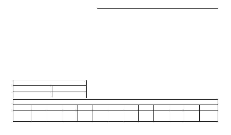
TERMINALS (Upper)
ALS (Upper)
ALS (Upper)
ALS (Upper)
ALS (Upper)
L
PH
Malfunction Light
Not Used
THERMOSTAT TERMINALS (Lower)
THERMOSTAT TERMINALS (Lower)
THERMOSTAT TERMINALS (Lower)
THERMOSTAT TERMINALS (Lower)
THERMOSTAT TERMINALS (Lower)
SYSTEM
E
C
R
W3/A1
W2
E2/P
W1
Y2
Y1
B
O
G
Multi-Stage
No function
24 Volt
24 Volt
Not Used
Heat mode
No function
Heat mode
Cool mode
Cool mode
Energized in Energized in
Blower/Fan
(Common)
(Hot)
2nd stage
1st stage
2nd stage
1st stage
Heat & Off
Cool mode
Energized on
mode
call for Cool*
* (and Heat if configured to Electric Heat)