Appendix a: technical reference, Period and frequency measurement – Casio EA-100 Technical Reference User Manual
Page 8
68
Appendix A: Technical Reference
Command 3:
{3,1,70}
3 = SAMPLING AND TRIGGER SETUP
1 = Sampling time (1 second)
70 = Number of samples
The manual trigger default is applied as the trigger
source.
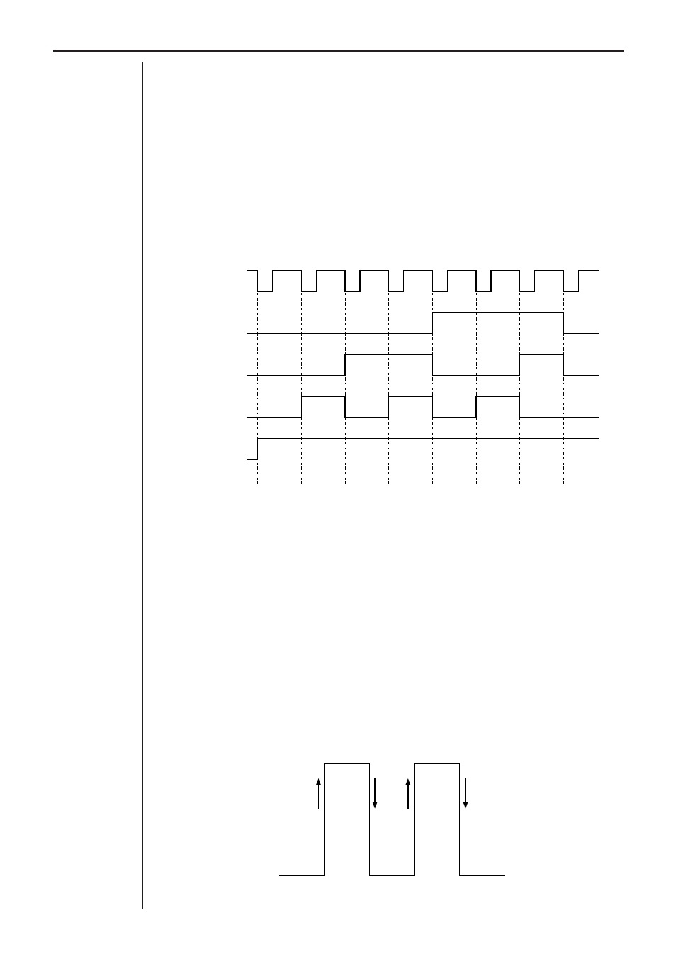
The DOB outputs signals that correspond to the seven data nibbles. This
sequences is repeated to the DIG OUT channel 10 times (70 samples/7 data
elements). The following diagram shows the output for the first seven data
elements.
1
3
5
7
9
11
13
1
Sampling
Clock
D3
D2
D1
D0
Period and Frequency Measurement
Period and frequency can be measured using Channel 1, Channel 2, or Chan-
nel 3 (simultaneous multiple-channel measurements are not allowed), and
only when the operation parameter is 5 (period) or 6 (frequency). Period and
frequency are measured on the Vin pin (pin 1). Period and frequency meas-
urements always use the hard trigger.
One of the two following methods is used for period and frequency measure-
ments.
A. Counting of the number of trigger edges for 0.25 second
B. Measuring the time between edges specified by Command 1 (see
illustration below)
0
T =
1
2
3