Installation, Fig. 1 – CarAlarms.com P90-NG1 User Manual
Page 28
Excalibur
®
P90 Zero Clearance Direct Vent Gas Fireplace
28
CONVERSION KIT #791-969 FROM NG TO LP
THIS CONVERSION MUST BE DONE BY A QUALIFIED GAS FITTER IF IN DOUBT DO NOT DO THIS CONVERSION !!
Each Kit contains one LPG
Conversion Kit and one DC
Sparker Kit.
LPG Conversion Kit Contains:
Qty. Part #
Description
1
904-529 5/32"
Allen
Key
1
904-645 Burner
Orifi
ce
#51
1
918-590
Label "Converted to
LPG"
1
908-528 Red
"LPG"
label
1
910-037
LP Injector (Pilot Orifi ce)
1
918-487 Instruction
Sheet
DC Sparker Kit Contains:
Qty. Part #
Description
1
820-475 Bracket
DC
Sparker
1
820-476 Bracket
DC
Sparker
1
904-153
Washer #8 External Star
1
904-330 Nut
8-32
Hex
1
904-438
Plug Nylon 0.750 Hole,
Black (for H35 only)
1
904-531
Bushing Split Plastic
0.500
in.
1
904-543
Screw 8-32 x 3/4 Pan
Head
2
904-553
Screw #8 x 1/2 Type "B",
Black
Oxide
1
910-073
Spark Generator Battery
Holder
1
910-074
Spark Generator Switch
C/W
Wire
1
910-078 Battery
Size
AA
Energizer
En91
2
910-199 Clip
Wire
Holder
1
910-903
Wire Fan To Power Cord
Ground 30 in.
904-781
Velcro Hook, Black
904-782
Velcro Hook, Black
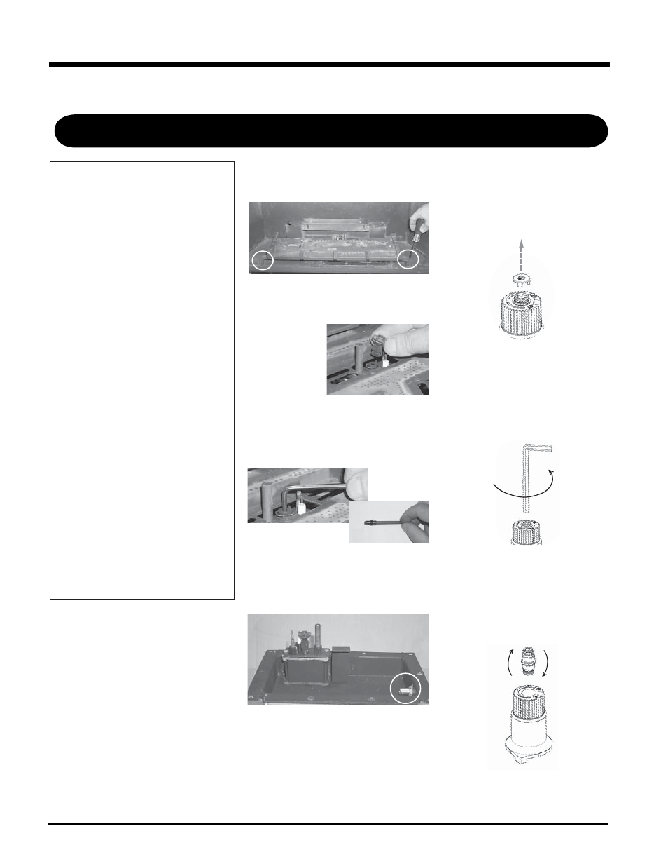
5)
Pull off the
pilot cap to
expose the
pilot orifi ce.
Remove the 2 screws, push Burner
Assembly to the left and lift out.
Burner Orifi ce
Installation of LPG
Conversion Kit:
1)
Shut off the gas supply.
2)
H35-1: Lift off the Cast Top and remove
the glass front. Also, open up the control
panel door.
P90-1: Remove the facade if it is in-
stalled. Remove the glass door (refer to
the glass door section in the manual).
3)
Remove the logs, embers, and brick
panels (if used).
4)
Remove the 2 screws holding the Burner
Assembly to the fi rebox base. Push the
Burner Assembly to the left and lift out.
6)
Unscrew the pilot orifi ce with the allen
key and replace with the LP pilot orifi ce in
the kit and replace pilot cap.
7)
Remove burner orifi ce with a 1/2" wrench
and discard. Use another wrench to hold
on to the elbow behind the orifi ce.
8)
Reinstall new burner orifi ce LP stamped
#51 and tighten.
9
)
Turn control knob to the “OFF”
position.
10
) Remove the black protection cap by
hand from the high-low knob (Fig.1).
Fig. 1
11
) Insert a 5/32” or 4mm Allen wrench
into the hexagonal key-way of the
screw (Fig. 2), rotate it counter-
clockwise until it is free and extract it.
12
) Check that the screw is clean and if
necessary remove dirt.
13
) Flip the screw (Fig. 3).
Fig.2
Fig.3
INSTALLATION