Leds, Leds 1-2, Table 1-1 – Enterasys Networks VSER-RPU-SYS User Manual
Page 14: Port status leds, Figure 1-2
About the Redundant Power Supply
1-2
1
LEDs
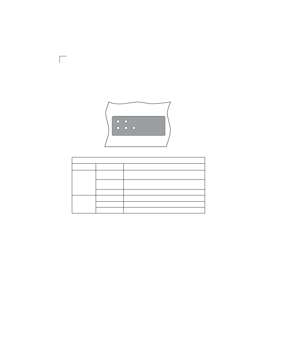
The following diagram and table describe the functions of the LEDs on the Front
Panel.
Figure 1-2. LEDs
Table 1-1. Port Status LEDs
LED
Condition
Status
RPS 1, 2, 3, 4
On Green
Power is being supplied to the RPS, the unit is functioning
normally, and the RPS port is connected to a switch.
Flashing Green
Power is being supplied to the RPS, the unit is functioning
normally, but no switch is connected to the RPS port.
Off
Power is off, or a failure has occurred.
Fan
On Green
The fans are functioning normally.
Flashing Red
One or more fans have failed.
Off
The unit is not connected to an AC power source.
Fan
1
2
4
3
VSER-RPU-SYS