Echo Trimmer User Manual
Page 11
P
OWER
P
RUNER
TM
A
TTACHMENT
O
PERATOR
'
S
M
ANUAL
11
S
PECIFICATIONS
Specifications, descriptions and illustrative material in this literature are as accurate as known at the time of publica-
tion, but are subject to change without notice. Illustrations may include optional equipment and accessories, and may
not include all standard equipment.
A
SSEMBLY
POWER
HEAD
SHAFT
/
LOWER
SHAFT
ASSEMBLY
Tools Required: None
Parts Required: Power Head Shaft, Pruner Lower Shaft Assembly
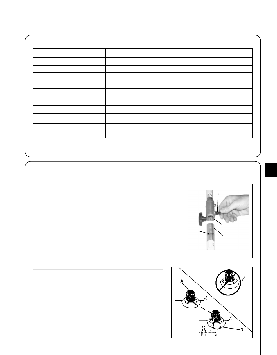
1.
Set Power Head/Pruner Shaft Assembly on a level surface.
2.
Pull locator pin (A) and rotate counter clockwise 1/4 turn to lock
out position.
3.
Carefully fit lower drive shaft assembly into coupler (B) to decal
assembly line (C), making sure that the inner lower flex cable
engages into the upper drive shaft coupler mount.
NOTE
Lower bearing housing and head assembly must be in line
with the engine.
4.
Rotate locator pin (A) 1/4 turn clockwise to engage lower shaft
hole (D). Insure locator pin is fully engaged by gently twisting
lower drive shaft assembly.
5.
Locator pin (A) should snap flush in coupler. Full engagement
will prevent further shaft rotation.
A
B
C
D
M O D E L
P O W E R P R U N E R
T M
AT T A C H M E N T
L e ng th
1 4 5 .5 c m (5 7 .2 5 in.)
W i d th
7 .0 c m (2 .7 5 in.)
H e ig ht
1 .2 7 c m (5 .0 in.)
W e i g ht
2 .0 k g (4 .4 5 lb s .)
S p ro c k e t Typ e
6 to o th s p ur, 9 .5 3 (3 /8 i n.) p i tc h
D rive S ha ft
1 /4 in. F le x C a b le
G e a r R e d uc tio n R a ti o
1 .5 :1
O iling S ys te m
A uto m a ti c
H a nd le
L e ft fo a m g ri p
G uid e B a r a nd S a w C ha i n
2 5 4 m m (1 0 in.), 9 .5 3 m m (3 /8 i n.) p i tc h