Empire Comfort Systems VFP32FP(20,21)L User Manual
Page 26
Page 26
20101-2-0806
CAUTION: ALL WIRING SHOULD BE DONE BY A QUALIFIED ELECTRICIAN AND SHALL BE IN COMPLIANCE
WITH ALL LOCAL, CITY AND STATE BUILDING CODES. BEFORE MAKING THE ELECTRICAL CONNECTION,
MAKE SURE THAT MAIN POWER SUPPLY IS DISCONNECTED. THE APPLIANCE, WHEN INSTALLED, MUST BE
ELECTRICALLY GROUNDED IN ACCORDANCE WITH LOCAL CODES OR, IN THE ABSENCE OF LOCAL CODES,
WITH THE NATIONAL ELECTRICAL CODE ANSI/NFPA 70 (LATEST EDITION).
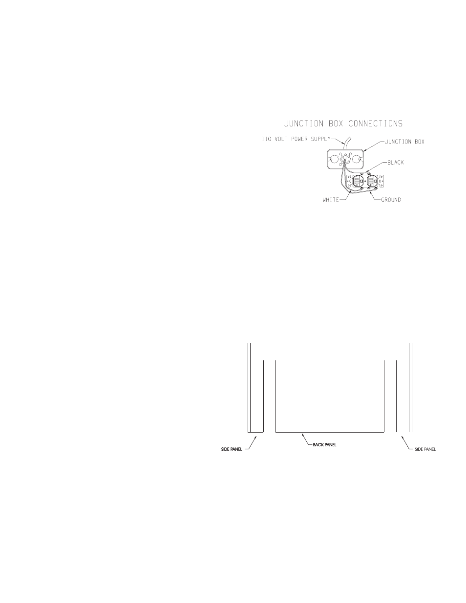
A factory installed junction box is located on the lower right
hand side of the fireplace. Wiring must be fed to the junction
box and attached to the receptacle that is provided. Remove the
knockout in the installed junction box to accept wiring into the
junction box. Install a UL listed cable clamp (not supplied) in the
knockout hole. Leave approximately 6" of wire in the junction
box for connection.
Attach black wire to one side of the receptacle and white wire to
opposite side of receptacle. The ground wire should be attached
to the green (neutral) screw.
Install the receptacle into the junction box. Attach cover plate.
Brick Liner VPP32A and VPP36A
1. Remove screen from fireplace.
2. Remove branch log and rear log from burner assembly.
3. Insert back panel into firebox.
4. Insert one (1) side panel into firebox.
5. Use two (2) brick panel brackets to secure side panel. Align
clearance hole on brick panel bracket with screw hole in the
left or right interior, top and bottom of firebox. Use two (2)
10 x 1/2" screws to attach brick panel bracket to interior top
and bottom of firebox.
6. Repeat steps 4 and 5 to install second side panel.
7. Replace rear log and branch log onto burner assembly.
8. Replace screen onto fireplace.
9. Installation of optional brick liner is completed.