Dimm replacement procedure, Removing the existing dimm, Installing the dimm – Enterasys Networks DFE-256MB-UGK User Manual
Page 3: D to, Dimm replacement, Procedure, Below
DIMM Replacement Procedure
PN 9033946
Page 3 of 5
DIMM Replacement Procedure
Although the following replacement procedure describes how to replace a DIMM in an angled
connector, the procedure also applies to DIMM replacement in a vertical connector.
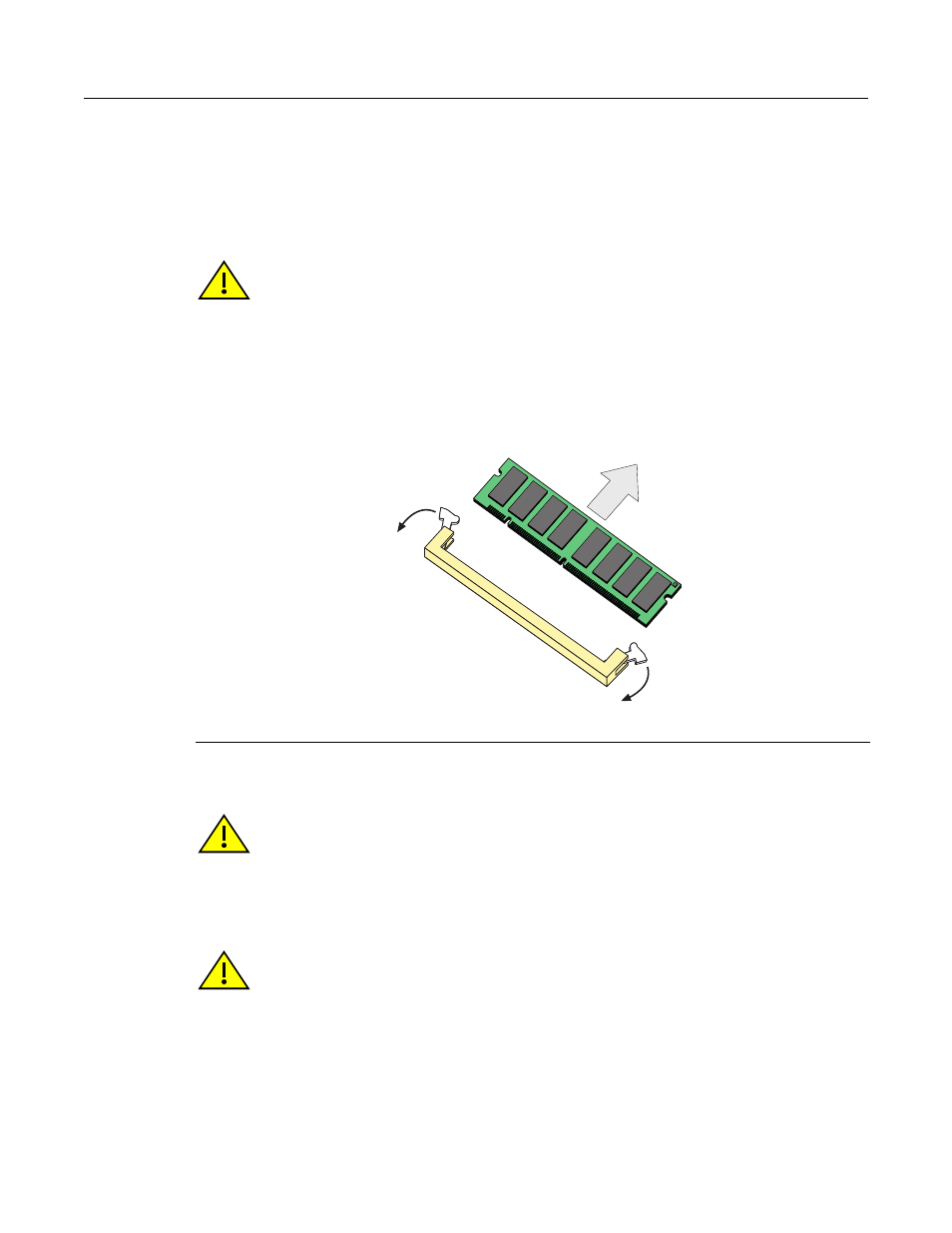
Removing the Existing DIMM
and proceed as follows:
1.
Push the connector arms
➀
away from the DIMM
➁
to release it from the connector
➂
.
2.
Remove the module from the connector
➂
.
Figure 1 Removing the Existing DIMM
Installing the DIMM
To install the memory module, refer to
and proceed as follows:
1.
With the connector arms
➀
set in the open position, insert the DIMM
➁
between the
connector fingers
➂
.
2.
Push the memory module into the connector until the tabs on the two connector arms pull in
towards the DIMM alignment notches
➄
.
Caution: Observe all antistatic precautions when handling sensitive electronic equipment.
➀
Connector arms
➁
DIMM
➂
Connector
В
А
А
Б
Caution: Observe all antistatic precautions when handling sensitive electronic equipment.
Caution: The connectors on different DFE modules may have the keys inside the connector
reversed. To prevent damaging the DIMM and main pc board, make sure that key slots
➃
are
positioned to match those in the connectors. Otherwise, the DIMM and pc board will be damaged.