Rear panel connections, Connecting the 3.5 mm mini-plugs, Figure 3. mps 409 rear panel – Extron Electronics MPS 409 User Manual
Page 12
Rear Panel Connections
50/60 Hz
L
R
Tx
MIC/LINE
IN
ON
OF
F
MIC
LINE
LEVEL
+48V
ON
1 2
HDMI
VIDEO
VGA/YUV
DVI-D
OUTPUT
OUTPUT
OUTPUT
OUTPUT
OUTPUT
OUTPUT
OUTPUT
1
2
L
1
2
1
2
1
2
1
2
1
2
1
2
3
3
1
2
L
L
R
R
R
MIC/LINE
PROGRAM
AUDIO
OUT
Rx
RS-232
OUTPUT
100-240V 0.4A MAX
j k
s t
u
a
b
c
d
f
g
h
i
e
l
n o
p
q
r
m
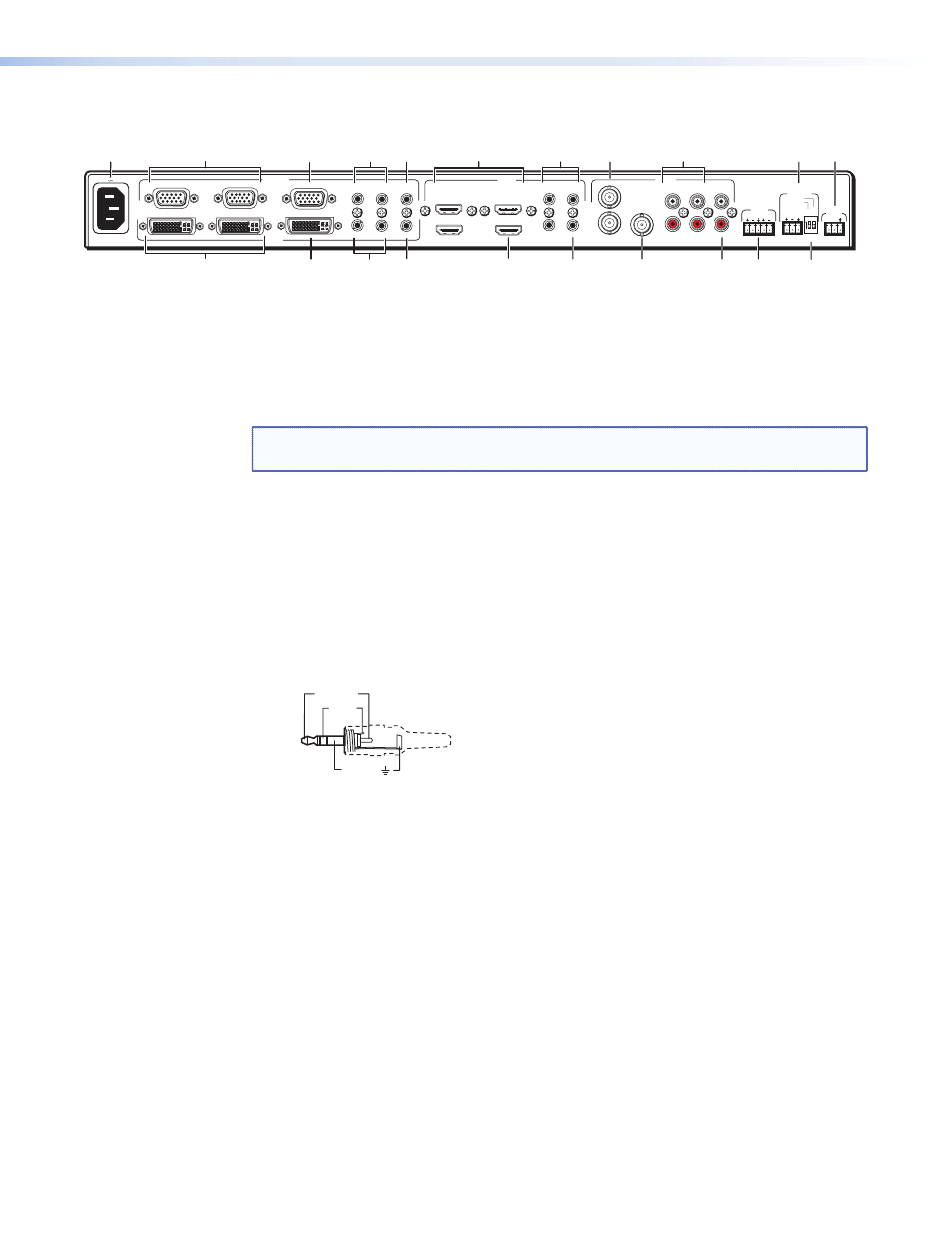
Figure 3.
MPS 409 Rear Panel
a
AC power — Connect to standard AC power: 100-240 VAC, at 50-60 Hz
b
VGA video input group — two female 15-pin HD connectors for VGA input
(numbered 1 and 2). the connectors accept VGA or YUV signals. For YUV signals, red
color channels are used for R-Y (Pr), blue color channels are used for B-Y (Pb), and green
color channels are used for Y.
NOTE: the MPS 409 does not scale or convert video. the input signal format will also
be the output format.
c
VGA video output — One 15-pin HD connector with the selected VGA/YUV video
output.
d
VGA audio inputs — two 3.5 mm stereo audio connectors corresponding to the
VGA video inputs. Each audio input can be adjusted from -18 dB to +24 dB.
Connecting the 3.5 mm mini-plugs
1.
Use pre-made Extron 3.5 mm stereo audio cables (see
www.extron.com
),
or
cut bulk audio cable and solder a 3.5 mm mini-plug to the cable as shown.
Tip (+)
Sleeve ( )
Sleeve ( )
Ring
(R+)
Tip (L+)
RCA Connector
3.5 mm Stereo Plug Connector
(unbalanced)
Figure 4.
3.5 mm, Mini-Plug Audio Connector
2.
Plug the connector into the MPS 409.
e
VGA audio output — One 3.5 mm stereo audio output connector with audio output
from the selected VGA input. Connect to the audio input of an audio amplifier. See
figure 4 above for wiring.
f
HDMI video input group — three HDMI connectors for HDMI compliant video
input (numbered 1 through 3). Connect to any HDMI source device using standard
HDMI cable.
g
HDMI audio inputs — three 3.5 mm stereo audio connectors corresponding to the
HDMI video input sources. See Figure 4 above for wiring.
h
Composite video input group — two BNC connectors for composite video
(numbered 1 and 2) from any composite video source device.
i
Composite audio inputs — Four RCA connectors for two stereo audio inputs
corresponding to the two composite video sources.
MPS 409 • Installation
6