Antenna considerations, Power control – Linx Technologies RXM-GPS-F4 User Manual
Page 7
–
–
–
–
8
9
Antenna Considerations
The F4 Series module is designed to utilize a wide variety of external
antennas, but care must be taken in antenna selection to ensure optimum
performance. For example, a handheld device may be used in many
varying orientations so an antenna element with a wide and uniform
pattern may yield better overall performance than an antenna element with
high gain and a correspondingly narrower beam. Conversely, an antenna
mounted in a fixed and predictable manner may benefit from pattern and
gain characteristics suited to that application. Evaluating multiple antenna
solutions in real-world situations is a good way to rapidly assess which will
best meet the needs of your application.
For GPS, the antenna should have good right hand circular polarization
characteristics (RHCP) to match the polarization of the GPS signals.
Ceramic patches are the most commonly used style of antenna, but
there are many different shapes, sizes and styles of antennas available.
Regardless of the construction, they will generally be either passive or
active types. Passive antennas are simply an antenna tuned to the correct
frequency. Active antennas add a Low Noise Amplifier (LNA) after the
antenna and before the module to amplify the weak GPS satellite signals.
For active antennas, a 300 ohm ferrite bead can be used to connect the
the RFIN line to an external supply for the antenna. This bead prevents the
RF from getting into the power supply, but allows the DC voltage onto the
RF trace to feed into the antenna. A series capacitor inside the module
prevents this DC voltage from affecting the bias on the module’s internal
LNA.
Maintaining a 50 ohm path between the module and antenna is critical.
Errors in layout can significantly impact the module’s performance. Please
review the layout guidelines elsewhere in this guide carefully to become
more familiar with these considerations.
Power Control
The F4 Series GPS Receiver module offers four power control modes:
Full Power, Adaptive Trickle Power, Push-to-Fix and Hibernate. In Full
Power mode the module is fully active and and continuously tracking.
Measurements are of the highest quality and are continuously output by the
module. This is the highest current consumption state.
In Adaptive Trickle Power mode, the receiver powers on at full power to
acquire and track satellites and obtain satellite data. It then powers off the
RF stage and only uses its processor (CPU) to determine a position fix.
Once the fix is obtained, the receiver goes into Hibernate mode. After a
user-defined period of time, the receiver wakes up to track the satellites for
a user-defined period of time, updates its position using the CPU only, and
then resumes standby. The initial acquisition time is variable, depending
on whether it is a cold start or assisted, but a maximum acquisition time is
definable. This cycling of power is ideal for battery-powered applications
since it significantly reduces the amount of power consumed by the
receiver while still providing similar performance to the full power mode.
Push-to-Fix mode is for applications that require infrequent position
reporting. The module stays in Hibernate mode until either the ON_OFF
line is triggered or a user-defined time period has expired. The Push-to-Fix
Period is set by a serial command and can be between 10 seconds and
two hours. An edge on the ON-OFF line triggers an immediate position fix.
When the module wakes up it acquires a new position fix and outputs the
NMEA messages before going back into Hibernate mode.
Hibernate mode is the lowest power setting. The tracking and processor
blocks are powered down, but the RTC is still running and the memory
blocks are still powered, enabling a hot start.
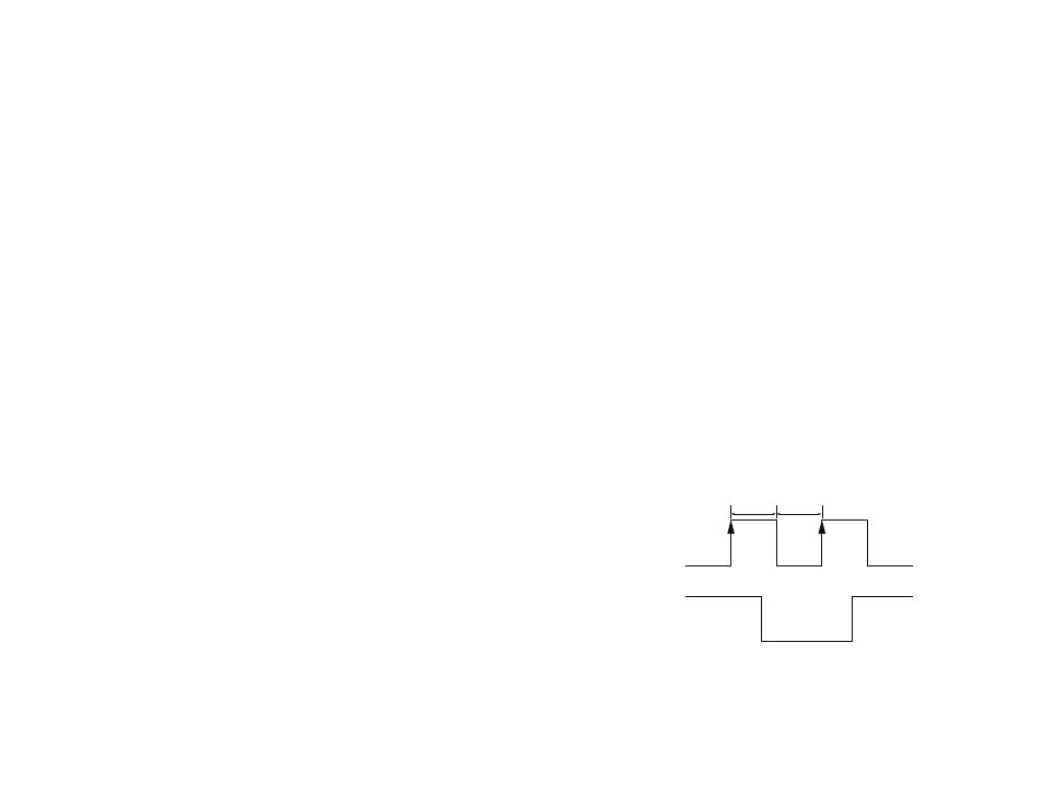
The module switches between these states by toggling the ON_OFF line.
The ON_OFF line must go high for at least 100ms to trigger the change of
state and must remain low for at least 100ms to reset the edge detector.
If the module is in Full Power mode, a pulse on the ON_OFF line initiates an
orderly shutdown into Hibernate mode. If the module is in Hibernate mode,
a pulse transistions the module into Full Power Mode. If the module is in
Push-to-fix mode a pulse initiates a single push-to-fix cycle. If the module is
in Adaptive Trickle Power mode, a pulse initiates one Trickle Power cycle.
ON_OFF
Full Power
Hibernate
Full Power
Module
Power
100ms
100ms
Figure 7: F4 Series GPS Receiver Power Control