Using the remote control demo board – Linx Technologies MDEV-xxx-RC User Manual
Page 7
–
–
–
–
8
9
Range Testing
Several complex mathematical models exist for determining path loss in
many environments. These models vary as the transmitter and receiver are
moved from indoor operation to outdoor operation. Although these models
can provide an estimation of range performance in the field, the most
reliable method is to simply perform range tests using the modules in the
intended operational environment.
Range testing can be performed with the Remote Control Demo Boards.
To prepare the board for range testing, simply turn it on by switching the
power switch to the ON position. Pressing a status line button on one
board (the IU) activates an LED on the other board (the RU). The RU then
sends an acknowledgement back to the IU, which turns on the CONFIRM
LED. This indicates good bi-directional RF communications and lets the
user set one board down and walk with the other board.
As the maximum range of the link in the test area is approached, it is not
uncommon for the signal to cut in and out as the radio moves. This is
normal and can result from other interfering sources or fluctuating signal
levels due to multipath effects. This results in cancellation of the transmitted
signal as direct and reflected signals arrive at the receiver at differing times
and phases. The areas in which this occurs are commonly called “nulls”
and simply walking a little farther usually restores the signal. If the signal is
not restored, then the maximum range of the link has been reached.
To achieve maximum range, keep objects such as your hand away from
the antenna and ensure that the antenna on the transmitter has a clear and
unobstructed line-of-sight path to the receiver board. Range performance
is determined by many interdependent factors. If the range you are able to
achieve is significantly less than specified by Linx for the products you are
testing, then there is likely a problem with either the board or the ambient
RF environment in which the board is operating. First, check the battery,
switch positions, and antenna connection. Next, measure the receiver’s
RSSI voltage with the transmitter turned off to determine if ambient
interference is present. High RSSI readings while the transmitter off indicate
there is interference. If this fails to resolve the issue, please contact Linx
technical support.
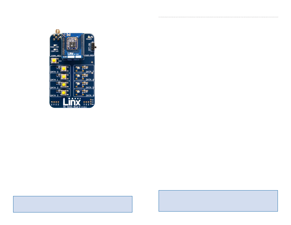
Using the Remote Control Demo Board
Snap a Carrier Board onto the socket on each Remote Control Demo
Board as shown in Figure 9.
Insert 4 AAA batteries into the holders on the back of each board, connect
antennas and turn on power.
The modules come paired out of the box, but to Pair additional modules,
press the PAIR button on both boards. The MODE_IND LEDs flash to
indicate that the modules are searching for each other and exchanging
addresses. The MODE_IND has a quick flash while searching (100ms on,
900ms off) and a longer flash once Pairing is complete (400ms on, 100ms
off). This process only takes a few seconds. The pairing process takes the
status line input / output directions into account. If these are changed then
the modules should be paired again.
Once complete, pressing a button on one board (the Initiating Unit or IU)
causes an LED to light up on the other board (the Responding Unit or RU).
The RU sends an acknowledgement message to the IU. If the message is
valid, the IU turns on the CONFIRM LED.
Figure 9: Remote Control Demo Board with a Carrier Board
Note:
The Remote Control Demo boards are designed for hardware
configuration. If the modules are changed through software configuration
then the boards may not operate as expected. A restore to default
configuration can be used to reset the modules.
Note:
To restore the default configuration, push the PAIR button four
times and hold it down on the fifth press. The MODE_IND LED flashes
when it has reset.