Linkskey LKS-FCM22T-2 User Manual
Page 2
LED Indicator
LED indicators serve as device monitoring and error display.
The following is the explanation for each LED indicator.
LEDs
State
Indication
On
Fiber link connection established
FX Link/Act
Blinking Transmitting or receiving data
On
TP link connection established
TP Link/Act
Blinking Transmitting or receiving data
On
Connection in full duplex mode
DUP
Off
Connection in half-duplex mode
PWR
On
Power on
SD
On
Fiber signal is detected
On
TP connection speed is 100Mbps
100
Off
TP connection speed is 10Mbps
Transmission characteristics of dual fiber converter
Dual Fiber
Transmitting
optical
power
(dBm)
Receiving
sensitivity
(dBm)
Transmission
maximum
distance
(km)
Loss
allowed
(dBm)
MM/ST/SC/
1310nm
-14 ~ -9
-34
2
10
SM/ST/SC/
1310nm
-13 ~ -4
-33
20
19
SM/SC/
1310nm
-8 ~ -3
-35
40
27
SM/SC/
1310nm
-5 ~ 0
-36
60
34
SM/SC/
1550nm
-8 ~ -3
-35
80
27
SM/SC/
1550nm
-5 ~ 0
-36
100
31
SM/SC/
1550nm
-2 ~ 3
-37
120
35
Transmission characteristics of single fiber converter
Single Fiber
Transmitting
optical
power (dBm)
Receiving
sensitivity
(dBm)
Transmission
maximum
distance
(km)
Loss
allowed
(dBm)
SM/ SC/
1310/1550nm
-13 ~ -6
-30
20
SM/ SC/
1310/1550nm
-8 ~ -3
-35
30
SM/ SC/
1310/1550nm
-6 ~ 0
-36
40 ~ 60
SM/ SC/
1310/1550nm
-3 ~ 3
-37
60 ~ 80
Standard
loss:
1310nm-
0.4/km
1550nm-
0.25/km
Main features
1. Built in 128KB RAM for data buffer
2. Half
-
duplex back
-
pressure and IEEE802.3x full duplex flow control
3.
Auto MDI/MDI-X detection function on the TP port
4. Forward 1600 bytes packets for management
5. Support link fault pass through function
6. Support far end fault function on the FX port
7. Power from external AC power adapter or USB bus-powered
8. DIP switch configurations
9. Built in watchdog timer monitoring internal state
10. LED status for link/activity, full/half-duplex, 10M/100M
11. Transmission distance 2km multi-mode, 120km single-mode
12.
Low power consumption
Technical parameters:
1. Standard: IEEE 802.3 10 Base-T standard,
IEEE 802.3u 100Base-TX/FX standard
2. Connector: one UTP RJ-45 connector, one SC/ST connector
3. Operation mode: full duplex mode or half-duplex mode
4. Power consumption: 5V DC 1A or USB bus-powered (3.0W max.)
5. Operation temperature: 0
℃ - 55 ℃ (32˚F - 131˚F)
6. Storage temperature: -20
℃ - 70 (
℃ -4˚F - 158˚F)
7. Relative humidity: 5% - 90%
8. TP cable:
10Mbps - Category 3, 4, or 5 UTP
100Mbps - Category 5 UTP
9. FX cable: Multi-mode - 50/125, 62.5/125 or 100/140µm
Single-mode - 8.3/125, 8.7/125, 9/125 or 10/125µm
10. Dimensions: 94mm x 70mm x 26mm (3.7in x 2.8in x 1.0in)
Cautions:
1. This product is suitable for indoor application.
2. Put on the dust cover of fiber interface when not used.
3. It is forbidden to stare at the TX fiber-transfer end with naked eyes.
Troubleshooting:
1. Fail to transmit data: Make sure the UTP distance does not exceed
100m, and the fiber distance does not exceed the maximum distance.
Verify that both nodes are running at the same speed.
2.
UTP or Fiber Link LED is not lit: Check the power on the
network device connected to the converter, make sure it is
turned ON. Check the cables, make sure the UTP cable
complies with EIA/TIA 568 specification and fiber optic
cables comply with industry standards.
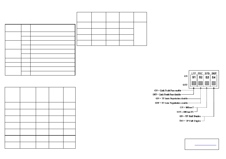
DIP switch settings:
Technical Support
E-mail:
Website: www.linkskey.com