Jumper settings, Chapter 3, Board layout – Lanner LEC-7105 User Manual
Page 13: Sct2 sct1
13
Board Layout
Chapter 3
Embedded and Industrial Computing
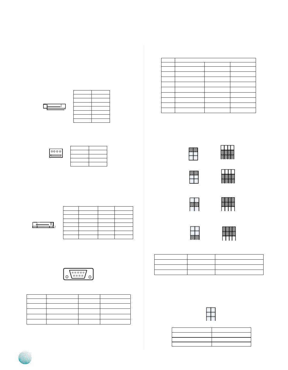
RS-232/422/485 Serial Port(COM2): It is a RS-232/422/485
port through the D-SUB9 connector.
SCT1, SCT2: Select COM2 Protocol Setting
RS-232
RS-422
RS-485
COM1 TYPE
SCT2
SCT1
RS-232 (Default)
1-2
1-5, 2-6, 3-7, 4-8
RS-422
3-4
5-9, 6-10, 7-11, 8-12
RS-485
5-6
5-9,6-10,7-11,8-12
JP1, JP2: Select COM1 and COM2 power : The Pin No.
9 of RS-232 can be altered to supply power. JP1 and JP2
are used to select the power voltage for COM1 and COM2
respectively.
Jumper Settings
Serial-ATA Connector (SATA1, SATA2): It is for connecting
a 2.5’’ harddisk to be served as your system’s storage. It
can support SATA II which features Data transfer rates up
to 3.0 Gb/s (300 MB/s).
4-pin Serial-ATA Power Connector (J3): It is for
connecting the SATA power cord.
Power eSATA Port (5V, EUSB1): A Power external SATA
port supports hot plugging of SATA II disc. It was provided
by the PCIe to SATA controller: JMB362 which connects
to the ICH8M through the PCIe interface. It can support
USB2.0 as well as eSATA transmission.
RS-232 Serial Port (COM1): It is a RS-232 port through
the D-SUB9 connector.
Pin No.
Pin Name
Pin No.
Pin Name
1
dCd
6
dSR
2
RXd
7
RTS
3
TXd
8
CTS
4
dTR
9
RIA
5
GNd
Pin No.
Function
1
GNd
2
TX0_+
3
TX0_-
4
GNd
5
RX0_-
6
RX0_+
7
GNd
RS-232 Pin 9 Function
JP1, JP2
+5V
1-2
+12V
3-4
RI (default)
5-6
LEB-7105
Pin No.
Function
1
+5V
2
GNd
3
GNd
4
+12V
1 2 3 4 5 6 7
4 3 2 1
Pin No.
Pin Name
RS-232
RS-422
RS-485
1
dCd
Txd-
data-
2
RXd
Txd+
data+
3
TXd
Rxd-
4
dTR
Rxd+
5
GNd
6
dSR
7
RTS
8
CTS
9
RI
SCT2
SCT1
1
3
5
2
4
6
9
5
1
12
8
4
5
3
1
6
4
2
S7 S6 S5 S4 S3 S2 S1
Pin No.
Function
Pin No.
Function
1
GNd
1
+5V
2
TX1_+
2
USB8+
3
TX1_-
3
USB8-
4
GNd
4
GNd
5
RX1_-
6
RX1_+
7
VCC5
1 2 3 4 5
6 7 8 9