Chapter 1, Introduction – Lanner LEC-3100 User Manual
Page 7
5
Introduction
Chapter 1
Embedded and Industrial Computing
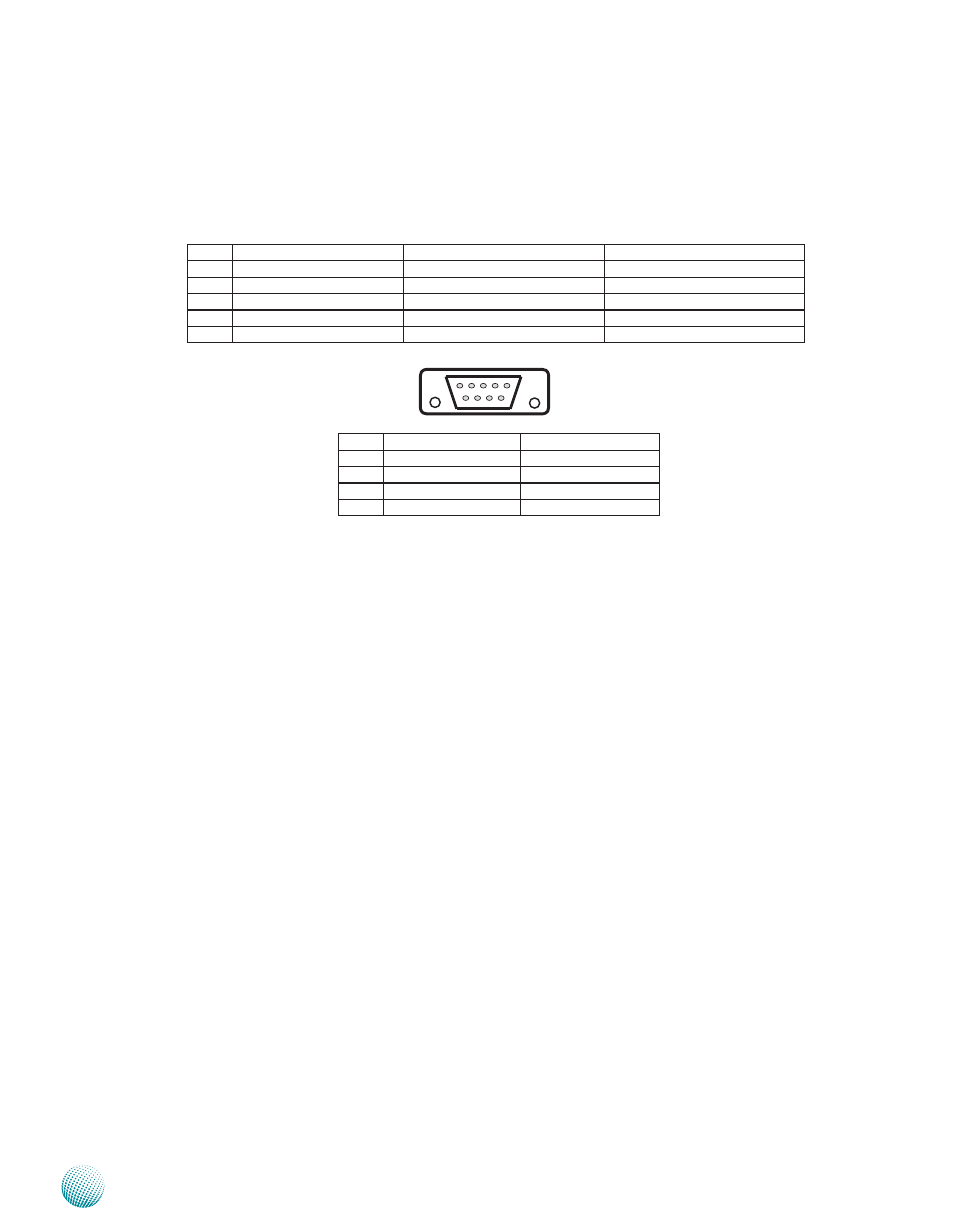
R6 Two RS-232 Serial Port (Right: COM1, Left: COM2)
These two serial ports have default operation mode of RS-232 communication channel, but can be configured
as either RS-422 or RS-485 serial communication channel through jumper selection Refer to Chapter 3
Motherboard Information for jumper selection information They are also isolated ports
R7 DVI-I Connector
It is a Dual Link DVI-I Connector which supports both digital and analog signals, allowing either type of monitor
(analog or digital) to be operated from the same connector (or with a special purpose DVI-A or DVI-I to VGA
cable) By using suitable DVI-I cable, you can connect an appropriate device; for example, an LCD panel
R8 Two USB 2 0 type A ports
It connects to any USB devices, for example, a flash drive There is another external port on the front panel and
one internal USB pitch connector on the mainboard
R9 One FastEthernet LAN port (LAN 5) and 4 Gigabit Ethernet LAN ports (LAN1-4)
LAN 5 is provided by Intel 82562GZ Ethernet controller which supports10/100Mbps connection speeds
LAN 1-4 are provided by Intel 82574L Ethernet controller which supports10/100/1000Mbps connection
speeds
Using suitable RJ-45 cable, you can connect LEC-3100 System to a computer, or to any other piece of equipment
that has an Ethernet connection such as a hub or a switch
Pin No.
Pin name for RS-232
Pin name for RS-485/RS-422
Pin name for RS-485(2 wires)
1
Data Carrier Detect (DCDA#)
TX-
D-
2
Received Data (RXDA)
TX+
D+
3
Transmitted Data (TXDA)
RX+
4
Data Terminal Ready (DTRA#)
RX-
5
Signal Ground (GND)
Ground (GND)
Ground (GND)
Pin No.
Pin name for RS-232
Pin name for RS-485
6
Data Set Ready (DSRA#)
7
Request to Send (RTSA#)
8
Clear to Send (CTSA#)
9
Ring Indicator (RIA#)
6 7 8 9
1 2 3 4 5