Jumper settings, Jumper settings 10, Chapter 3 – Lanner LEC-3100 User Manual
Page 12: Motherboard information
10
Motherboard Information
Chapter 3
Embedded and Industrial Computing
Jumper Settings
SATA Connector (J2): The system supports one SATA 2 5”
drive
The Intel ICH7 provides hardware support for Advanced
Host Controller Interface (AHCI) which is a programming
interface for SATA host controllers AHCI provides advanced
performance and usability enhancements with SATA such
as Hot-Plug and NCQ (Native Command Queing)
Note: To configure your Hard disk using the
AHCI feature, you need to enable the AHCI
option in the hard disk configuration of the BIOS
menu
SATA Power Connector (CON1): Connect the 4-pin SATA
power connector to this port
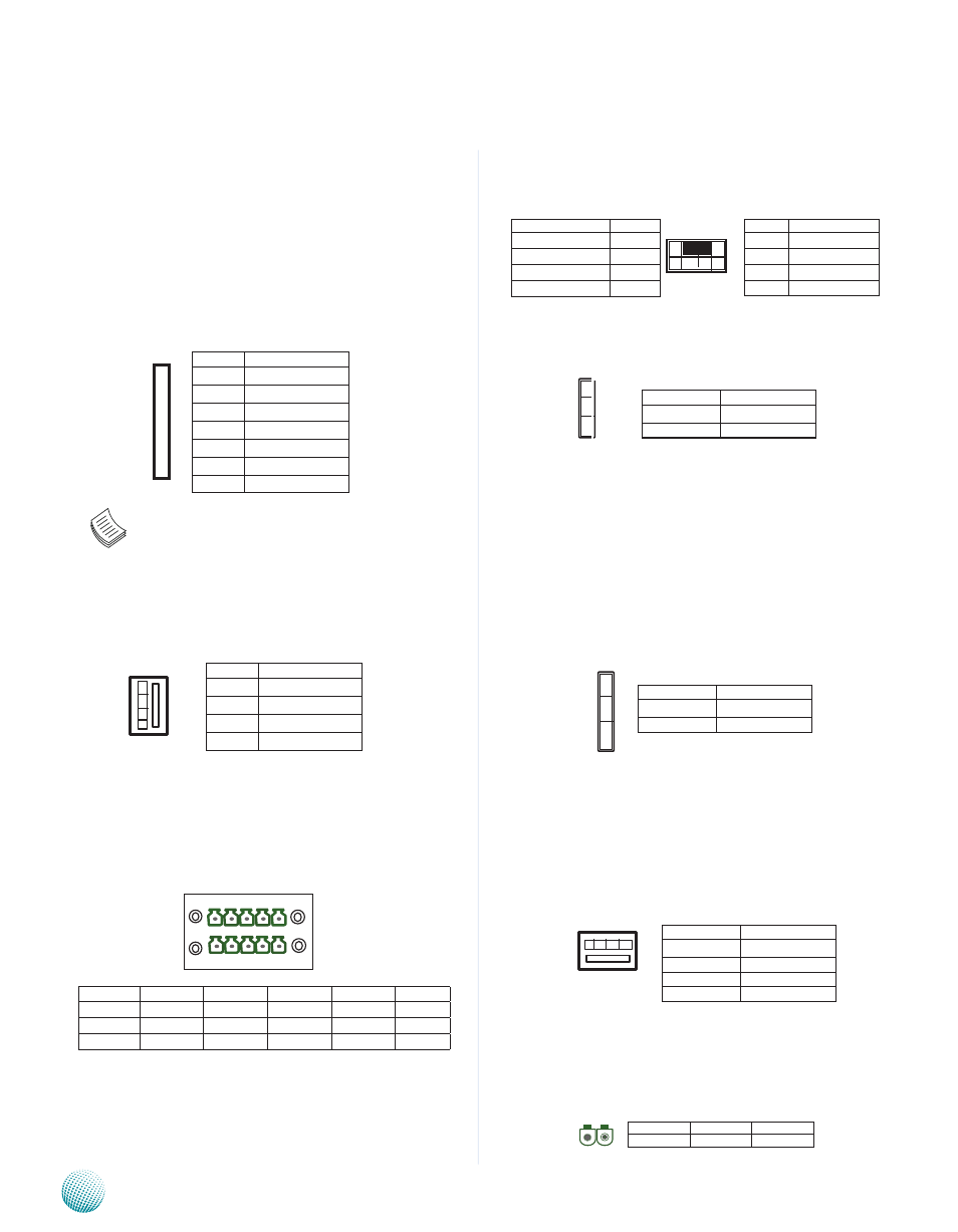
Digital I/O Connector (CN8): This connector provides 4
digital inputs and 4 digital outputs The connector type
of LEC-3100 is a plug-in screw terminal block that enables
you to connect to field I/O devices directly
Digital Inputs/Output Requirements
Logic 0: 0 ~ 2V DC
Logic 1: 2 ~ 5V DC
Current limit: Maximum 100mA for each pin
Keyboard and mouse interface Connectors(J3): It is
for connecting the PS/2 keyboard and mouse interface
cable
Clear CMOS jumper (J1): It is for clearing the CMOS
memory and system setup parameters by erasing the data
stored in the CMOS RAM such as the system passwords
CompactFlash Connector (CN4): It is for connecting a
Compact Flash card to be served as your system’s storage
The connector is a CF Type II slot which could fit both CF
Type I or CF Type II cards
CompactFlash Primary/Slave Selection Jumper (J5):
The system’s CompactFlash connects to LEC-3100’s
Primary IDE port in parallel with IDE connector J13 This
jumper configures the CF socket to be the Master (default)
or Slave IDE device
SO-DIMM Socket (CN1): The 200-pin DDR2 SO-DIMM is
for connecting the DDR2 533 MHz memory The system
can support up to 2GB in maximum
Mainboard DC Power Input Connector (PS1): Attach the
4-wires DC power cable to the power input terminal block
on the mainboard The system has an ATX-style power
input (VDC 24V) and system control
Phoenix Power Contact (CN9): It is a power socket for
power supply (9~36 VDC) through Phoenix Contact The
connector provides protection for reversed wiring of
ground line and power line
7
6
5
4
3
2
1
Pin No.
Function
1
GND
2
TX+
3
TX-
4
GND
5
RX-
6
RX+
7
GND
Pin No.
1
2
3
4
5
Function
Input 0
Input 1
Input 2
Input 3
Ground
Pn No.
6
7
8
9
10
Function
Output 0
Output 1
Output 2
Output 3
Ground
5 4 3 2 1
1 0 9 8 7 6
Pin No.
Function
2
MSCLK
6
KEY
6
KEY
8
KBCLK
Function
Pin No.
5V
1
MSDATA
3
KBDATA
5
GND
7
Pin No.
Function
2-3
Master (Default)
1-2
Slave
1 2 3 4
Pin No.
Function
1
DC+ (+24V)
2
DC+ (+24V)
3
DC-(GND)
4
DC-(GND)
Pin No.
1
2
Function
DC +/-
DC -/+
12
4
3
2
1
Pin No.
Function
1
NC
2
GND
3
GND
4
+5V
3
2
1
1 3 5 7
2 4 6 8
Pin No.
Function
1-2
Normal (Default)
2-3
Clear CMOS
1
2
3