Rear panel features, Rear panel features 4, Chapter 1 – Lanner LEC-3100 User Manual
Page 6: Introduction
4
Introduction
Chapter 1
Embedded and Industrial Computing
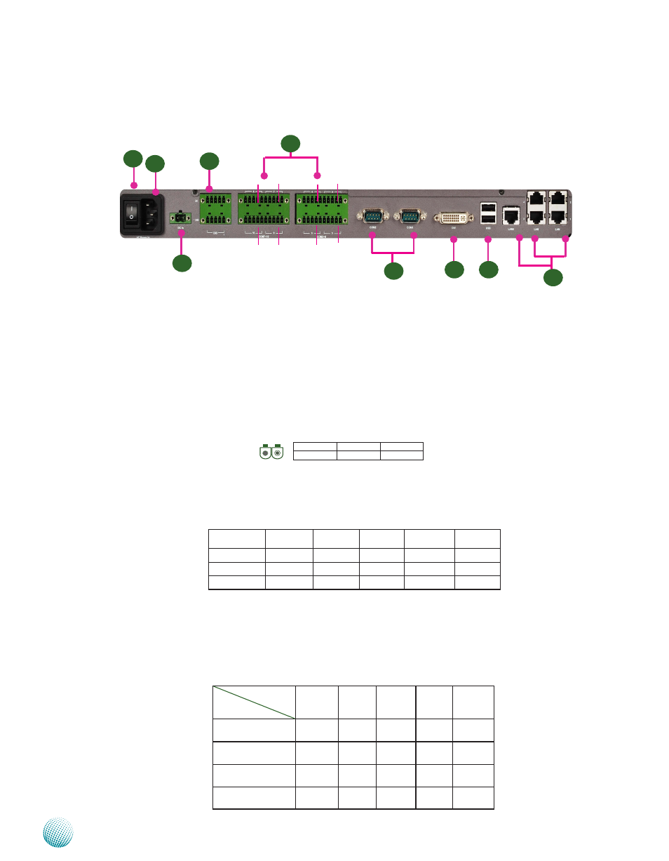
Rear Panel Features
R1 Power Switch
The power switch comes with the switch which can be used to turn on/off the power from the power
supply
R2 Power Socket
The AC inlet comes from the unit’s built-in 150W open frame power
R3 Redundant Power Supply Socket
A redundant power supply through 1x2-pin Phoenix Contact with 9~36V is provided on the system The
socket also features reversed wiring protection Hence, it will not cause any damage to the system by reversed
wiring of ground line and power line
R4 Digital Input/Output port:
The general-purpose input/output (GPIO) peripheral is provided through 10-pin terminal block connector
Pin 1to 4- Digital Inputs Pin 6-9-Digital Output
R5 20-pin Phoenix Contact Terminal Block
This terminal block can be connected as 8 Com ports with serial port type of RS-232, RS-422 or RS-485; it
supports dip switch selection among RS-232, RS-422 and 485 The following table lists the pin assignments
Refer to Chapter 3 Motherboard Information for dip switch adjustment information Note that Pin 1 starts
from right. These connectors are isolated COM ports which will protect system from being damaged due to
power surge or failure of the connected devices
R7
R8
R6
Pin NO.
Port Type
Pin 1
Pin 2
Pin 3
Pin 4
Pin 5
RS-232
SOUT
RTS
SIN
CTS Ground
(GND)
RS-422
TX+
TX-
RX-
RX+ Ground
(GND)
RS-485
TX+
TX-
RX-
RX+ Ground
(GND)
RS-485 (2 wires) D+
D-
Ground
Pin NO.
Pin 1
Pin 2
Pin 3
Pin 4
Pin 5
Assignment
Input 0
Input 1
Input 2
Input 3 Ground
Pin NO.
Pin 6
Pin 7
Pin 8
Pin 9
Pin 10
Assignment
Output 0 Output 1 Output 2 Output 3 Ground
LAN 2
LAN 4
LAN 1
LAN 3
LAN 5
R9
COM1
COM2
R2
R1
R3
R4
Pin 1
Pin 1
Pin 1
Pin 1
Pin 1
Pin 1
Pin 1
5 4 3 2 1
10 9 8 7 6
Pin 1
COM5
COM3
COM4
COM6
COM7
COM8
COM9
COM10
R5
Pin No.
1
2
Function
DC +
DC-
12