Front panel features, Chapter 1, Introduction – Lanner FW-7575 User Manual
Page 8
3
Introduction
Network Application Platforms
Chapter 1
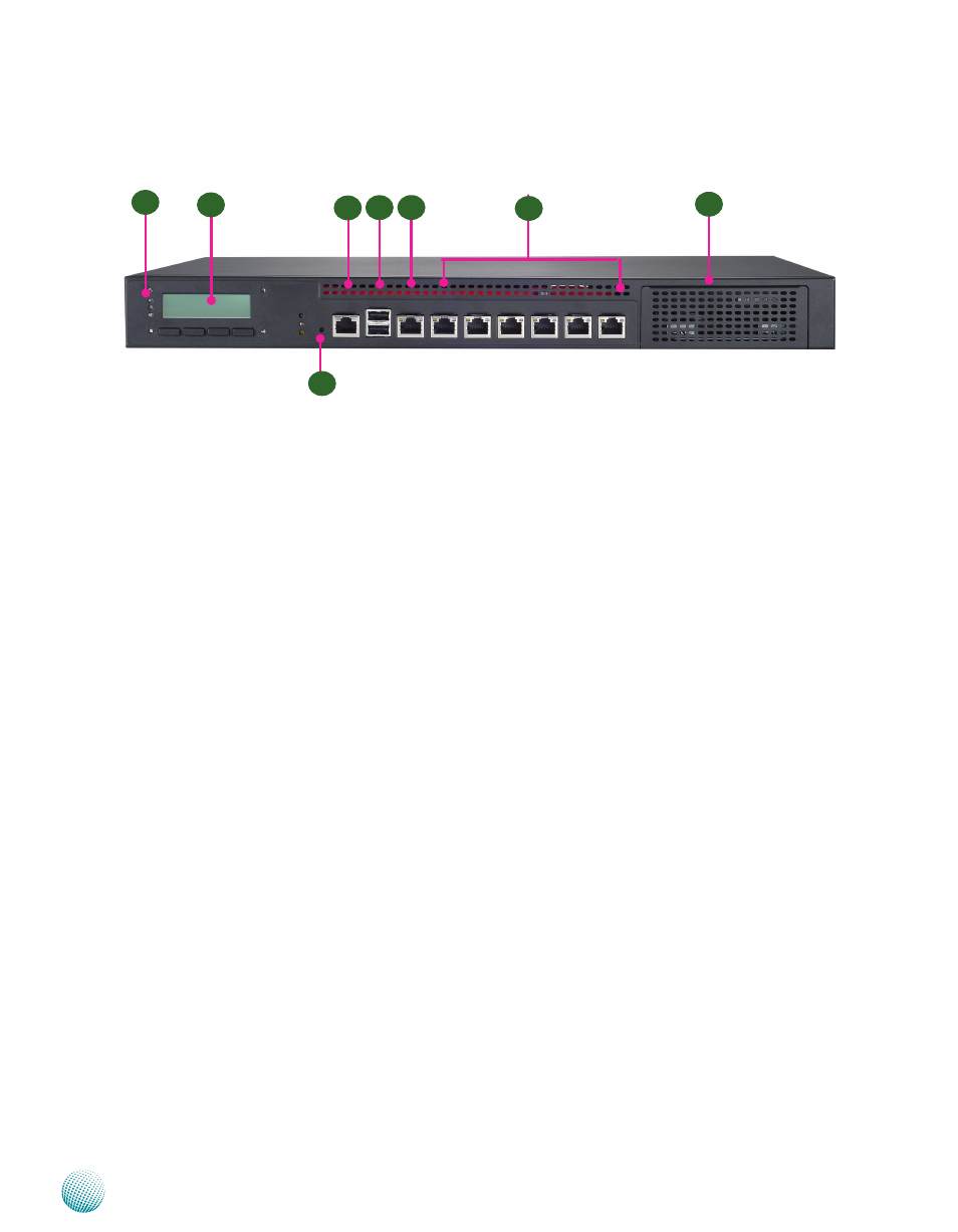
Front Panel Features
F1 Power/Status/HDD LED
Power: If the LED is on it indicates that the system is powered on. If it is off, it indicates that the system is powered off.
Status: This LED is programmable. You could program it to display the operating status with the following behavior:
If the LED is green, it indicates that the system’s operational state is normal. If it is red, it indicates that the system is
malfunctioning.
HDD:
If the LED blinks, it indicates data access activities; otherwise, it remains off.
F2 LCD System Panel
The LCD System Panel can be programmed to display operating status and configuration information. For more details or
sample programming code, please browse the Drivers and user’s manual CD.
F3 Console Port
By using suitable rollover cable or RJ-45 to DB-9 console cable, you can connect to a computer terminal for diagnostic or
configuration purpose. Terminal Configuration Parameters: 115200 baud, 8 data bits, no parity, 1 stop bit , no flow control.
F4 Two USB 2.0 Ports
It connects to any USB devices, for example, a flash drive.
F5 Management Port (provided by Intel 82574L)
This gigabit Ethernet port can be connected for configuration or troubleshooting purpose. You can also enable the Preboot
eXecution Environment (PXE) remote boot in the BIOS on this port (in the BIOS menu: Advanced->PXE).
F6 Reset Switch
The reset switch can be used to reboot the system without turning off the power.
F7 Ethernet Ports (LAN3-LAN4: bypass pair; LAN5-LAN6: bypass pair)
1
LINK/ACT (Yellow)
On/Flashing: The port is linking and active in data transmission.
•
Off: The port is not linking.
•
SPEED (Green/Amber)
Amber: The connection speed is 1000Mbps.
•
Green: The connection speed is 100Mbps
•
Off: .The connection speed is 10Mbps.
•
4 on-board Ethernet ports with 2 pairs of LAN bypass. These 6 GbE ports are provided by Intel Ethernet 82580DB and i347.
The management port (provided by Intel 82574L) is capable of Preboot eXecution Environment (PXE) (This feature needs to
be enabled or disable in the BIOS; the default is disabled). LAN1 and LAN2 are based on the Intel 82580DB , they are built
F1
F2
F3
F4
F5
F7
Management
(Intel 82574L)
F6
LAN1 LAN2
(Intel 82580DB) (Intel 82580DB)
LAN3 LAN4 LAN5 LAN6
(Intel i347) (Intel i347) (Intel i347) (Intel i347)
F8
(bypassed pair) (bypassed pair)