Chapter 2, System components – Lanner LVC-5550S User Manual
Page 10
10
System Components
Chapter 2
Embedded and Industrial Computing
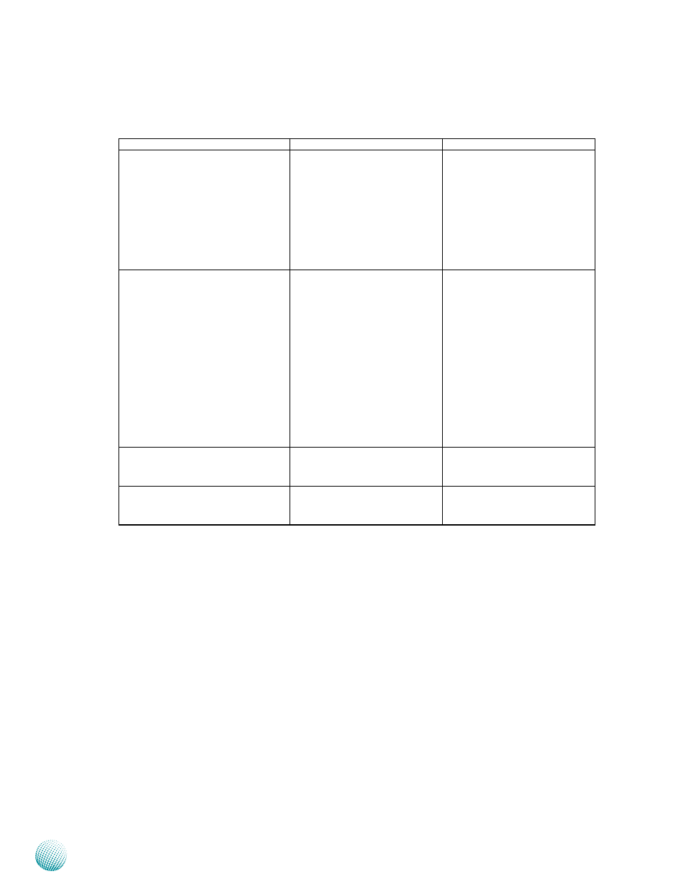
Component
Description
Pin Definition Reference
F6 HDD (Yellow) and
Power LED (Green)
HDD
Blinking: data access
•
activities
Off: no data access
•
activities
Power
On: The computer is on.
•
Off: The computer is off .
•
LED1 on page 18
F7 External Power Switch through
terminal block
A Power on/off switch
connector.
Short Press:
•
Power off the
system with the proper
procedure just like the
shutdown program on
Windows.
Long Press: Power off the
•
system without the proper
procedure, i.e., force to
shutdown (reserved func-
tion for systems without
power ignition control.
CN1 on page 17
F8 Power-on Button with Dual LED ATX power-on button with LEDs:
stand-by mode in red; power-
on mode in green.
PSBTN1 on page 18
F9 Hard Disk Slot
External SATA hard disk drive for
easy access and replacement of
the data storage.
SATA1 (data) and CON2 (SATA
power) on page 15
- LVC-2000 (39 pages)
- LVC-5000(N4) (42 pages)
- LVC-5570 (48 pages)
- LVC-5770 (49 pages)
- FW-6432 (16 pages)
- FW-7525 (41 pages)
- FW-5330 (38 pages)
- FW-6486 (18 pages)
- FW-6436 (19 pages)
- FW-7573 (44 pages)
- FW-7568 (52 pages)
- FW-7540 (47 pages)
- FW-8759 (47 pages)
- FW-7581 (23 pages)
- FW-8758 (42 pages)
- FW-7610 (44 pages)
- FW-8756 (24 pages)
- FW-7575 (48 pages)
- FW-8760 (53 pages)
- FW-8877 (46 pages)
- FW-8892 (58 pages)
- FW-8893C (49 pages)
- FX-3411 (48 pages)
- FW-8894 (31 pages)
- FW-8771 (47 pages)
- RS12-38800 (64 pages)
- MR-320 (20 pages)
- FX-3210 (54 pages)
- MR-301 (16 pages)
- MR-350 (12 pages)
- MR-330A (16 pages)
- MR-730 (18 pages)
- VES-220 (19 pages)
- VES-270 (19 pages)
- VES-310 (15 pages)
- VES-310 V2 (20 pages)
- VES-500 (21 pages)
- EM-F345 (30 pages)
- VES-8X2 (16 pages)
- VES-8X6 (17 pages)
- LEC-2026 (67 pages)
- LEC-2010 (65 pages)
- LEC-2136 (20 pages)
- LEC-2050 (38 pages)