2) wire sizes, For three-phase, 200v – Yaskawa Sigma-5 Series User Manual:: For Use with Large-Capacity Models-Setup. Rotary Motors User Manual
Page 70
3 Wiring and Connection
3.4.4 Main Circuit Wires
3-22
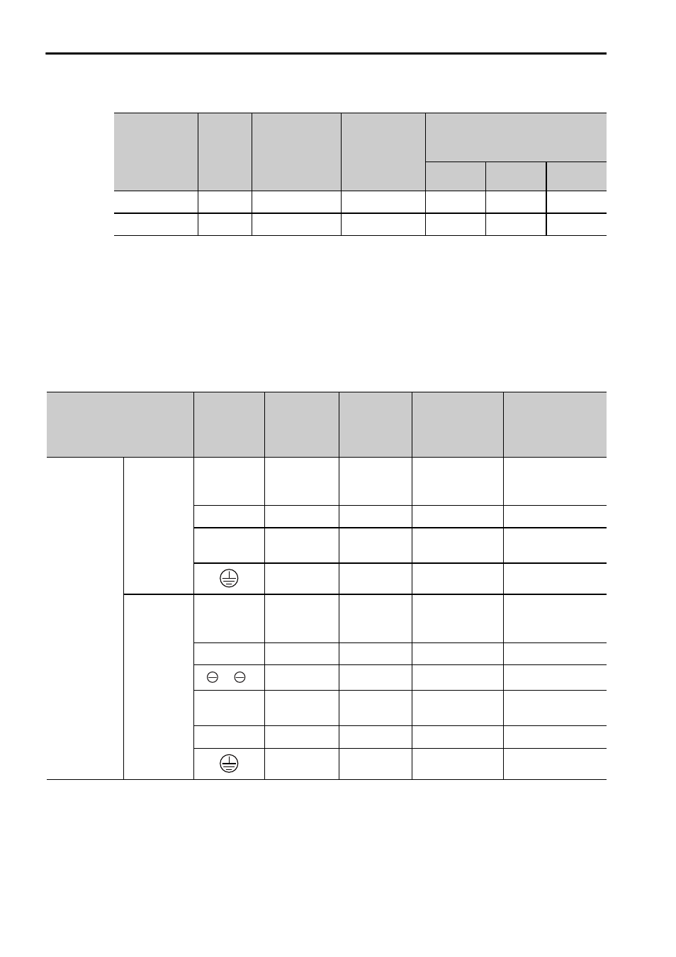
Note: These are reference values for 600-V-grade, heat-resistant, PVC-insulated wire.
(2) Wire Sizes
The following table shows the symbols for the power input terminals, screw sizes for
terminals, tightening torque, wire sizes, and crimp terminals used for the SERVO-
PACKs and converters.
For Three-phase, 200V
60
(2/0)
19/2.0
0.30
170
150
127
100
(4/0)
19/2.6
0.18
240
212
179
(cont’d)
Nominal
Cross
Section
Diameter
(mm
2
)
AWG
Size
Configuration
(Number of
Wires/mm)
Conductive
Resistance
(
Ω/km)
Allowable Current at
Surrounding Air Temperature
(A)
30
°C
40
°C
50
°C
Combination of
SERVOPACK and
Converter
*1
Terminal
Symbols
Screw Size
for
Terminals
Tightening
Torque
(Nxm)
HIV Wire Size
in mm
2
(AWG)
Crimp Terminal
Model
(Made by J.S.T.
Mfg Co., Ltd.)
*2
SGDV-121H
SGDV-
COA2BAA
SERVO-
PACK
P, N
M8
15.0
Bus bar
attached to the
converter
–
U, V, W
M8
3.0
60 (2/0)
R60-8
DU, DV,
DW
M6
3.0 5.5
(10)
R5.5-6
M8
9.0 to 1.0
60 (2/0)
R60-8
Converter
P, N
M8
3.0
Bus bar
attached to the
converter
–
L1, L2, L3
M8
3.0
38 (1)
R38-8
1, 2
M8
3.0 38
(1)
R38-8
CN101
(L1C, L2C)
–
(Connector)
–
1.25 (16)
–
B1, B2
M8
3.0
8 (8)
R8-8
M8
9.0 to 11.0
38 (1)
R38-8