Iqpump 7 ac drive, Simplex quick start procedure, Page 4 of 4 – Yaskawa iQpump 7 AC Drive User Manual
Page 4
Step
7
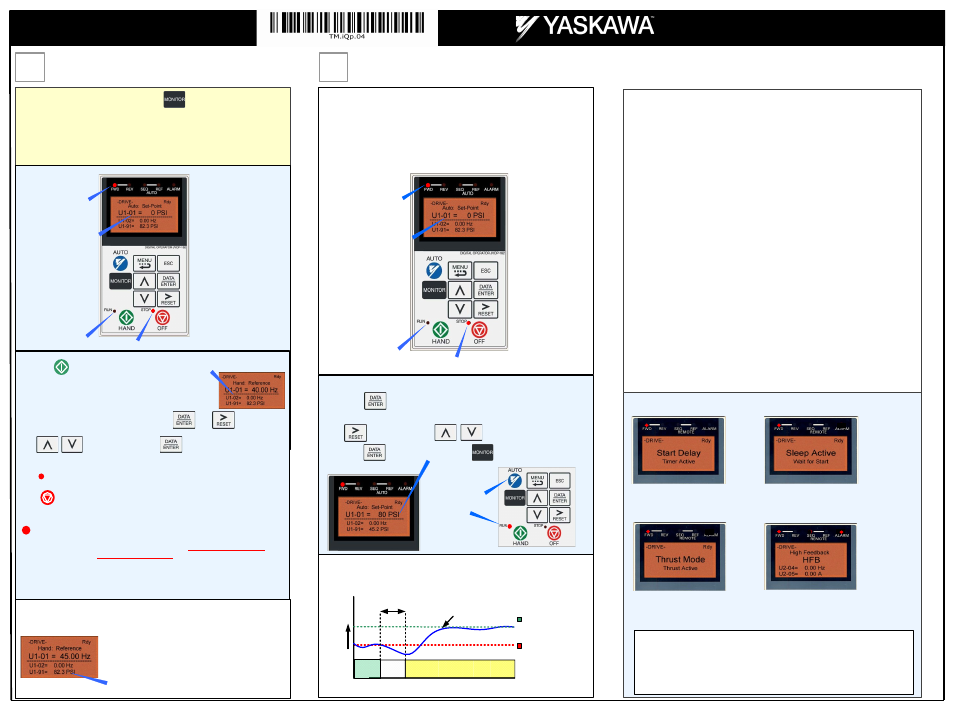
Auto Mode Operation
Step
6
Pump Rotation and Feedback Signal Check
Displays when the iQpump is about to
start. The feedback level has fallen below
the Start Level (P1-04) and the start delay
timer is active. Once the Start Level Delay
Time (P1-05) expires the iQpump will start.
Displays when the iQpump is in “sleep”
mode or when the iQpump is waiting for
the feedback level to drop below the Start
Level (P1-04).
Displays when “Thrust Bearing” mode is
active. To enable, enter value in parameter
P4-05
The feedback level has risen above P1-09
level for the time specified in P1-10. High
feedback fault is active in Hand Mode,
Auto Mode, Pre-Charge and Thrust Mode
when the iQpump is running.
TYPICAL DISPLAY MESSAGES
Yaskawa Electric America, Inc.
2121 Norman Drive South
Waukegan, IL 60085
(800) YASKAWA (927-5292) / Fax (847) 887-7310
[email protected]
www.yaskawa.com
YEA Document Number: TM.iQp.04 5/08/2013
© 2009 Yaskawa Electric America, Inc.
Sleep and Anti-No-Flow (ANF) Detection
NOTE: Before adjusting Anti-No-Flow operation ensure your system is regulating
satisfactory while operating under normal running conditions.
If stable continue to Step 1 to verify no-flow/sleep operation. If unstable turn off the
Anti-No-Flow function (P2-23 = 0.00%) and adjust the PI control parameters b5-02
and b5-03 to stabilize pump system. Refer to iQpump User Manual
(Document No. TM.iQp.06) for additional information. Once the system is stable,
re-enable the Anti-No-Flow function by setting P2-23 to 0.40% and continue to Step 1
to verify no-flow/sleep operation.
Step 1: Verify system holds pressure by creating a no-flow situation (e.g. close off
discharge valve).
Step 2: Press OFF button on the digital operator, wait 1 min. until system stabilizes
and verify system pressure feedback U1-91. If the pressure drops more than 3 PSI
(U1-91) adjust P2-25 to the actual delta pressure drop plus 1 PSI.
Example:
Set-point is 80 PSI, pressure feedback U1-91 shows 76 PSI, P2-25 should
be 4 + 1 or 5 PSI. N
Note: This value should always be more than your start level
(P1-04). If not, the system pressure is not holding and this needs to be corrected, or
the pump system will continue to cycle on and off.
Step 3: Run system in normal automatic operation with flow. Next check monitor
U1-99 “ANF Timer” and verify that the value is incrementing and resetting back to zero
continuously. If the value holds at 10 sec. (P2-24) increase P2-24 “Anti-No-Flow
Detection Time” by increments of 5 sec. Repeat Step 3 each time P2-24 is adjusted.
Step 4: Create a no-flow situation (e.g. close discharge valve) and monitor that U1-99
“ANF Timer” increments and holds at P2-24 time (value set in Step 3). Once the
Anti-No-Flow timer expires the speed will reduce gradually until it reaches minimum
pump speed (P1-06) where it will hold for 5 sec. (P2-03) before going to sleep.
Step 5: Run system in normal automatic operation and verify sleep and wake-up
operation until system performs satisfactory.
(P2-23, P2-24, P2-25)
Fig. 5 Digital Operator
Next, push
RUN
LED should be ON.
OFF
Using Safety precaution, and referring to Fig.1 or 2, swap any two of the three output
leads to the pump motor (U/T1, V/T2 and W/T3). After the wiring change repeat
Step 6 and recheck motor direction.
The motor should now be operating at low speed in the correct direction of pump.
Push
If the direction is not correct, then power down the iQpump.
on the digital operator; the display should read
on the digital operator; the display should read as in Fig. 3.
In this step the pump motor is checked for proper direction and operation. This test is to
be performed solely from the digital operator. Apply power to the iQpump after all the
electrical connections have been made and the terminal cover has been reattached. At
this point,
DO NOT RUN THE MOTOR
, the digital operator should display as shown
below in Fig. 5.
DANGER, LETHAL VOLTAGES ARE PRESENT- Before applying power to the
iQpump, ensure that the terminal cover is fastened and all wiring connections
are secure. After the power has been turned OFF, wait at least five minutes until
the charge indicator extinguishes completely before touching any wiring, circuit
boards or components.
!
Hand reference speed can be adjusted by pressing , use to move cursor
and to adjust the value. Press to save changes.
Verify feedback on display (show keypad) matches mechanical pressure gauge.
FEEDBACK SIGNAL CHECK
FEEDBACK SIGNAL LEVEL
Refer to parameter P1-02 and P1-03, if the feedback
device scaling or system units are incorrect.
When Pump Quick Setup is completed, press to exit the Pump Quick Setup
menu and go to operation.
FWD LED
ON
01 Flashing
RUN LED OFF
STOP LED ON
HAND
FWD LED
ON
Fig. 6 Digital Operator
01 Flashing
Next, press
to access or modify the system set-point that was entered using
iQpump can be operated in automatic mode when the following actions have been
performed:
x All parameters are programmed
x Pump motor direction has been checked
x Feedback signal has been checked
SET SYSTEM SET-POINT
iQpump automatically starts in Auto Mode when the feedback signal level falls below
the programmed level in parameter P1-04 for the specified time in P1-05.
At this point,
DO NOT RUN THE MOTOR
, the digital operator should display as shown
below in Fig. 6.
Use
to select the digit and
to change the system set-point.
Next press
Next, press the AUTO
button to start the
iQpump.
Start Pump System
Start
Delay
145 PSI
Start Level P1-04
System Set-Point
(Example 80 PSI)
Feedback signal from
pressure transducer
(4 – 20 mA)
0
Pressure
Start Level Delay (P1-05)
(Example 5.0 sec.)
WAIT
to store set-point and press
operation menu.
to return to the main
Refer to Illustration 2 on Page 2 of 4 for additional information on the Start Level Function.
parameter d1-01 System Set-point in the Pump Quick Setup Menu
Example: 80 PSI
RUN LED OFF
STOP LED ON
Page 4 of 4
iQpump 7 AC Drive
(Software 0034)
Simplex Quick Start Procedure