3 new and modified software functions – Yaskawa V1000 Traverse Application Custom User Manual
Page 13
3 New and Modified Software Functions
YASKAWA AMERICA, INC. TM.V1000SW.029 Traverse Application V1000 Custom Software Supplement
13
■
Application Example
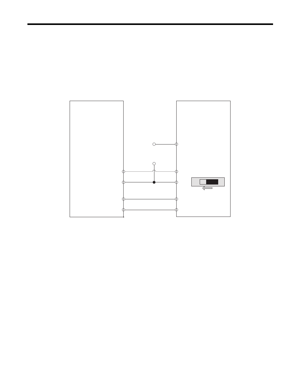
In the application shown in
, the slave drive is configured to run at its own
frequency reference provided at terminal A1. The Anti-Phase Slave Ripple Frequency
component is connected to analog input terminal A2 of the slave drive, with terminal bias
and offset set so that the Slave Ripple Frequency component alone will be a bipolar signal
oscillating around 0 Hz. This signal, summed with the Slave Frequency Reference at
terminal A1, sets the overall frequency reference for the drive.
Figure 1
Figure 1 Software and Hardware Configuration for V1000 Traverse
Master Parameter Changes:
• P1-01 = 1: Enable Traverse functionality.
• P1-02 to P1-05 = application requirements: Define the characteristics of the disturbed
frequency.
• P1-06 = application requirement: Define scan offset to account for system delays.
• H2-01 = 41h: Provide during disturb status output to slave.
• H4-01 = 703: Provide disturbed frequency ripple to slave.
Slave Parameter Changes
• C1-03 = 0.0 sec: Set acceleration time 2 to 0.0 sec.
• C1-04 = 0.0 sec: Set deceleration time 2 to 0.0 sec.
• H1-07 = 7: Switch between accel/decel time 1/2 based on During Disturb output.
• DIP Switch S1 = V: Enable voltage input to A2.
• H3-09 = 1: Set A2 to a 0 to 10V bipolar input.
• H3-11 = 50.0%: Set the gain to equate a 10 V signal to 30 Hz (50% of E1-04).
• H3-12 = -50.0%: Set the bias to equate a 0 V signal to -30 Hz (-50% of E1-04).
H2-01 = 41
H4-01 = 703
AM
AC
MA
MC
V1000 (Master)
Traverse Software
+
Slave
Frequency
Reference
-
A2
AC
S7
SC
H1-07 = 7
H3-09 = 1
H3-11 = 50
H3-12 = -50
A1
V1000 (Slave)
Standard Software
DIP Switch S1
V
I