Default settings, Non-default settings – Yaskawa SmartTrac DM6420 Multi I/O Card User Manual
Page 16
Smart Trac DM6420 Multi I/O Card
12
••
Configuring the Smart Trac DM6420 Multi I/O Card Technical Manual
Default Settings
The Smart Trac DM6420 Multi I/O card is shipped from the factory already
configured for the typical installation. The default values are:
•
JP1: Not Used.
•
JP2: Not Used.
•
D/A output voltage range for DAC1 (JP3): ±5 volts (–5 to +5 volts).
•
D/A output voltage range for DAC2 (JP4): ±5 volts (–5 to +5 volts).
•
Port 0 Pullup/Pulldown Resistors: Pull up is default.
•
Port 1 Pullup/Pulldown Resistors: Pull up is default.
•
Base I/O Address (Switch S1): 0x0300 hex (768 decimal).
Non-Default Settings
Whenever possible, you should use the defaults for all cards of your Smart Trac
Card stack. However, certain unusual situations will require non-default settings.
This may be necessary, for instance, if two Smart Trac DM6420 Multi I/O cards
are used in the stack.
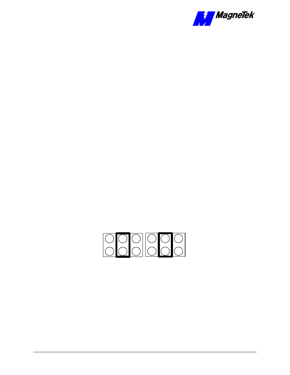
D/A output voltage range for DAC1 (JP3): You may change the setting to 0 to
+5, ±5V, or +10 V. This setting does not have to be the same as for DAC2
(JP4).
0 to +5 Volts
-5 Volts to +5 Volts
0 to +10 Volts
Jumper JP3
0 to +5 Volts
-5 Volts to +5 Volts
Jumper JP4
0 to +10 Volts
Figure 4.
Default jumper positions for JP3 and JP4.
D/A output voltage range for DAC2 (JP4): You may change the setting to 0 to
+5, ±5V, or +10 V. This setting does not have to be the same as for DAC1
(JP3).
Pullup resistors for Port 0 and Port 1 may be changed to Pulldown resistors if
required for your application. Contact your MagneTek Application Engineer if
you need bits pulled down or no resistors.
The Base I/O Address must be set to avoid conflicts with other cards or it will
not function properly. You may select a different base I/O address but you must
make sure to avoid address conflicts with other cards in your Smart Trac system.
DAC1 (JP3)
DAC2 (JP4)
Pullup/Pulldown
Resistors
Base I/O Address
Switch S1