Yaskawa SmartTrac Digital User Manual
Page 12
SMART TRAC AC1
6
••
The Smart Trac AC1 Digital Operator Engineer's Guide Smart Trac Digital Operator
data including parameters, feedbacks and selection and use of special
functions.
•
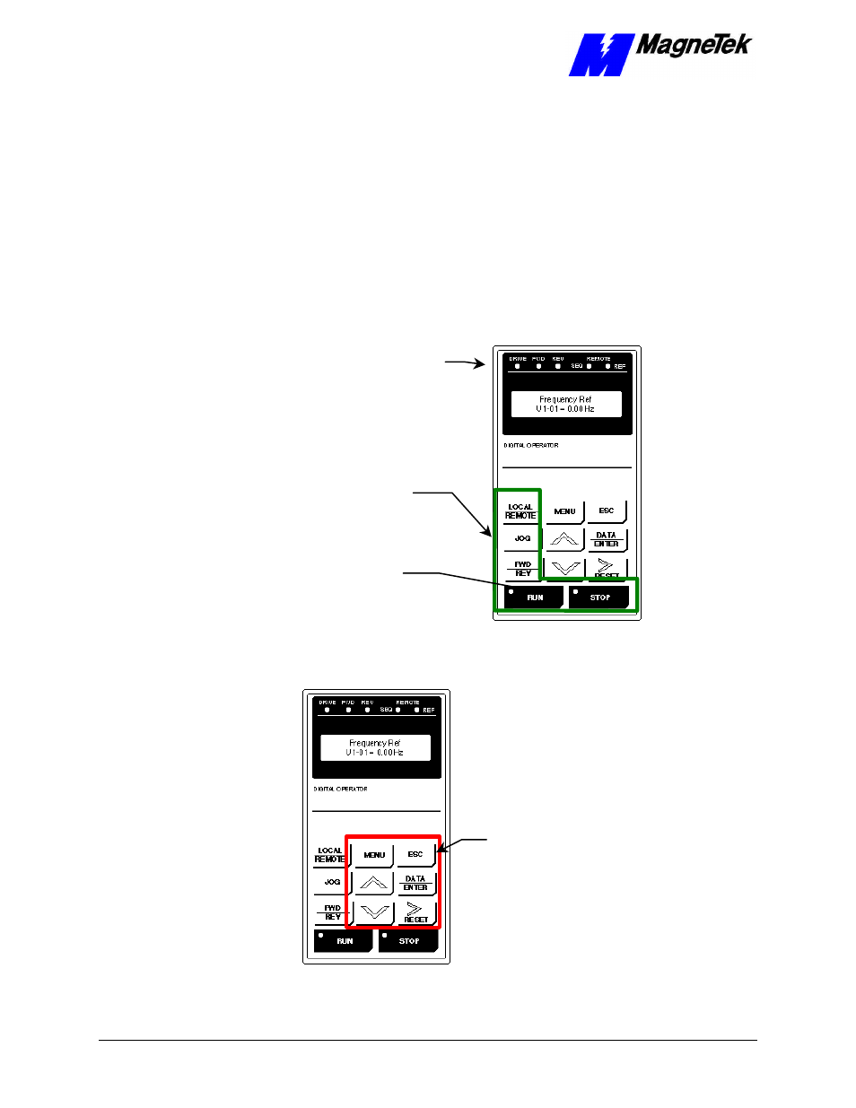
The CONTROL group includes the keys labeled LOCAL/REMOTE,
JOG, FWD/REV, RUN and STOP. These keys provide control over
the operation of the Smart Trac AC1. Although labeled for "typical"
use, they may be programmed to operate differently. Consult the
documentation specific to your Smart Trac AC1.
Indicators include seven status lights labeled DRIVE, FWD, REV,
REMOTE/SEQ and REMOTE/REF, RUN and STOP, and the LCD display
showing status, fault or parameter information. What causes these lights to be
triggered on or off is entirely up to the application program.
The behavior of each of these controls and indicators is described in tables and
the figures that follow:
Indicator
Lights
CONTROL
Group
RUN/STOP
Indicator
Lights in
Buttons
Figure 5.
The CONTROL Group of the Smart Trac AC1 Digital Operator.
DATA
Group
Figure 6
. The DATA group of the Smart Trac AC1 Digital Opertor.
Indicators
- Tag Generator (30 pages)
- MP3300iec (82 pages)
- 1000 Hz High Frequency (18 pages)
- 1000 Series (7 pages)
- PS-A10LB (39 pages)
- iQpump Micro User Manual (300 pages)
- 1000 Series Drive Option - Digital Input (30 pages)
- 1000 Series Drive Option - CANopen (39 pages)
- 1000 Series Drive Option - Analog Monitor (27 pages)
- 1000 Series Drive Option - CANopen Technical Manual (37 pages)
- 1000 Series Drive Option - CC-Link (38 pages)
- 1000 Series Drive Option - CC-Link Technical Manual (36 pages)
- 1000 Series Drive Option - DeviceNet (37 pages)
- 1000 Series Drive Option - DeviceNet Technical Manual (81 pages)
- 1000 Series Drive Option - MECHATROLINK-II (32 pages)
- 1000 Series Drive Option - Digital Output (31 pages)
- 1000 Series Drive Option - MECHATROLINK-II Technical Manual (41 pages)
- 1000 Series Drive Option - Profibus-DP (35 pages)
- AC Drive 1000-Series Option PG-RT3 Motor (36 pages)
- Z1000U HVAC MATRIX Drive Quick Start (378 pages)
- 1000 Series Operator Mounting Kit NEMA Type 4X (20 pages)
- 1000 Series Drive Option - Profibus-DP Technical Manual (44 pages)
- CopyUnitManager (38 pages)
- 1000 Series Option - JVOP-182 Remote LED (58 pages)
- 1000 Series Option - PG-X3 Line Driver (31 pages)
- SI-EN3 Technical Manual (68 pages)
- JVOP-181 (22 pages)
- JVOP-181 USB Copy Unit (2 pages)
- SI-EN3 (54 pages)
- SI-ET3 (49 pages)
- MECHATROLINK-III (35 pages)
- EtherNet/IP (50 pages)
- SI-EM3 (51 pages)
- 1000-Series Option PG-E3 Motor Encoder Feedback (33 pages)
- 1000-Series Option SI-EP3 PROFINET (56 pages)
- PROFINET (62 pages)
- AC Drive 1000-Series Option PG-RT3 Motor (45 pages)
- SI-EP3 PROFINET Technical Manual (53 pages)
- A1000 Drive Option - BACnet MS/TP (48 pages)
- 120 Series I/O Modules (308 pages)
- A1000 12-Pulse (92 pages)
- A1000 Drive Software Technical Manual (16 pages)
- A1000 Quick Start (2 pages)
- JUNMA Series AC SERVOMOTOR (1 page)
- A1000 Option DI-101 120 Vac Digital Input Option (24 pages)