Installation diagrams, Hdr1 jumper positions, Front view – Yaskawa VS-616PC5/P5 Isolated 4-20mA Output Monitor Card CM-B2/P User Manual
Page 5: Side view, Cm-b2/p
Page 5
VS-616PC5/P5 Option Instruction Manual: Isolated Monitor Card CM-B2/P
Note: Default 4 to 20mA
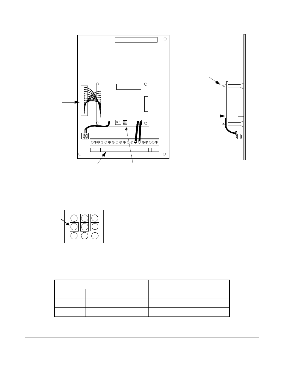
HDR1 Jumper Positions
HDR1 JUMPER POSITIONS
OUTPUT TB1
1-2
4-5
7-8
0 to 10 VDC
2-3
5-6
8-9
4 to 20 MA
1-2
4-5
8-9
0 to 20 MA
2
2CN option
connector
Fig. 2 Installation of Isolated Monitor Card CM-B2/P
Connector
terminal
FRONT VIEW
CM-B2/P
SIDE VIEW
Stand Off Posts (4)
CM-B2/P
TB1
TB2
1
HDR1
G
N
D
7
3
6
0
0
-D
0
1
2
0
C
O
D
E
N
O
.
TP1
Refer to Fig. 3
1
1
1
12
S1 S2
AM AC
S3
Fig. 3 Output Signal Configuration
3
6
9
2
5
8
1
4
7
JUMPER
for
HDR1
HDR1
3
6
9
2
5
8
1
4
7
HDR 1
Configures Output Signal at TB1
Note:
The three jumpers on the HRD1 are used to configure the
output signal at TB1. Refer to Table 2 for additional data.
See also other documents in the category Yaskawa Equipment:
- Tag Generator (30 pages)
- MP3300iec (82 pages)
- 1000 Hz High Frequency (18 pages)
- 1000 Series (7 pages)
- PS-A10LB (39 pages)
- iQpump Micro User Manual (300 pages)
- 1000 Series Drive Option - Digital Input (30 pages)
- 1000 Series Drive Option - CANopen (39 pages)
- 1000 Series Drive Option - Analog Monitor (27 pages)
- 1000 Series Drive Option - CANopen Technical Manual (37 pages)
- 1000 Series Drive Option - CC-Link (38 pages)
- 1000 Series Drive Option - CC-Link Technical Manual (36 pages)
- 1000 Series Drive Option - DeviceNet (37 pages)
- 1000 Series Drive Option - DeviceNet Technical Manual (81 pages)
- 1000 Series Drive Option - MECHATROLINK-II (32 pages)
- 1000 Series Drive Option - Digital Output (31 pages)
- 1000 Series Drive Option - MECHATROLINK-II Technical Manual (41 pages)
- 1000 Series Drive Option - Profibus-DP (35 pages)
- AC Drive 1000-Series Option PG-RT3 Motor (36 pages)
- Z1000U HVAC MATRIX Drive Quick Start (378 pages)
- 1000 Series Operator Mounting Kit NEMA Type 4X (20 pages)
- 1000 Series Drive Option - Profibus-DP Technical Manual (44 pages)
- CopyUnitManager (38 pages)
- 1000 Series Option - JVOP-182 Remote LED (58 pages)
- 1000 Series Option - PG-X3 Line Driver (31 pages)
- SI-EN3 Technical Manual (68 pages)
- JVOP-181 (22 pages)
- JVOP-181 USB Copy Unit (2 pages)
- SI-EN3 (54 pages)
- SI-ET3 (49 pages)
- MECHATROLINK-III (35 pages)
- EtherNet/IP (50 pages)
- SI-EM3 (51 pages)
- 1000-Series Option PG-E3 Motor Encoder Feedback (33 pages)
- 1000-Series Option SI-EP3 PROFINET (56 pages)
- PROFINET (62 pages)
- AC Drive 1000-Series Option PG-RT3 Motor (45 pages)
- SI-EP3 PROFINET Technical Manual (53 pages)
- A1000 Drive Option - BACnet MS/TP (48 pages)
- 120 Series I/O Modules (308 pages)
- A1000 12-Pulse (92 pages)
- A1000 Drive Software Technical Manual (16 pages)
- A1000 Quick Start (2 pages)
- JUNMA Series AC SERVOMOTOR (1 page)
- A1000 Option DI-101 120 Vac Digital Input Option (24 pages)