Yaskawa MicroTrac Gateway to Allen-Bradley Data Highway Plus for use with Microtrac LAN User Manual
Page 3
Introduction
3
Drive Description
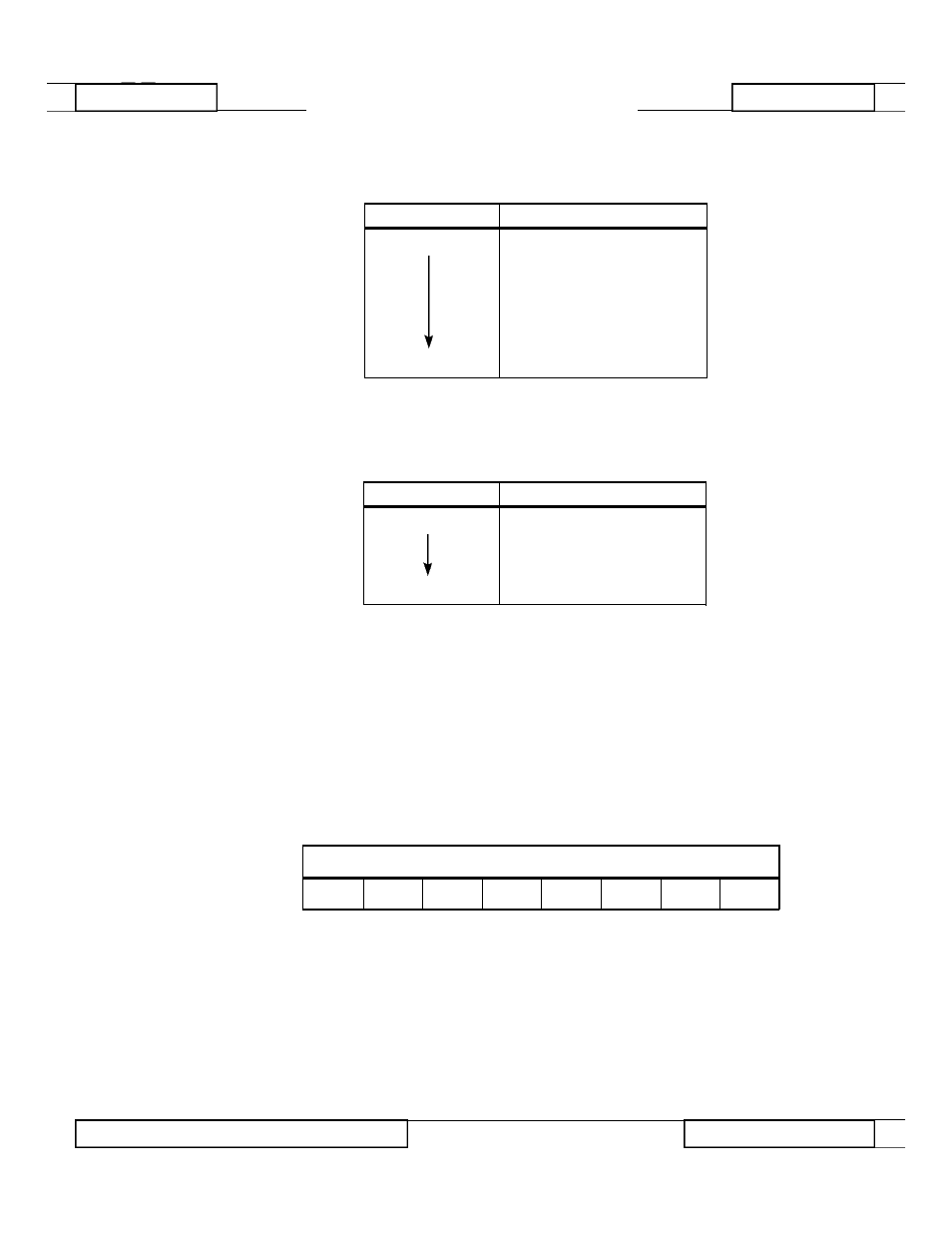
Install jumper plugs on E1 as shown in Table 1:
Install jumper plugs on E4 as shown in Table 2:
No jumpers are installed on E3.
The node ID is set using the 8-position DIP switch, SW1. Enter the binary node
ID by choosing either a "0" or "1" for each bit. The least significant bit (LSB)
and the most significant bit (MSB) positions are labeled on the board. The LSB
is toward the top of the board. Leaving the switch in the down position sets the
switch at "0". For example, node ID 200, represented in binary form as 11 0 0
1000, is set as shown in Table 3:
2
HARDWARE
MicroTrac Network Interface Card
M i c r o Tr a c
N e t w o r k
Interface Card
Table 1. E1 Settings
POSITION
JUMPER
TOP
YES
YES
NO
NO
NO
YES
NO
BOTTOM
YES
Table 2. E4 Settings
POSITION
JUMPER
IRQ2
NO
YES
NO
NO
IRQ7
NO
Table 3. Network Interface Card DIP Switch SW1 Settings
MSB
LSB
UP
UP
DN
DN
UP
DN
DN
DN
RD 906-20
© 1994 MagneTek, Inc.
94-04
- Tag Generator (30 pages)
- MP3300iec (82 pages)
- 1000 Hz High Frequency (18 pages)
- 1000 Series (7 pages)
- PS-A10LB (39 pages)
- iQpump Micro User Manual (300 pages)
- 1000 Series Drive Option - Digital Input (30 pages)
- 1000 Series Drive Option - CANopen (39 pages)
- 1000 Series Drive Option - Analog Monitor (27 pages)
- 1000 Series Drive Option - CANopen Technical Manual (37 pages)
- 1000 Series Drive Option - CC-Link (38 pages)
- 1000 Series Drive Option - CC-Link Technical Manual (36 pages)
- 1000 Series Drive Option - DeviceNet (37 pages)
- 1000 Series Drive Option - DeviceNet Technical Manual (81 pages)
- 1000 Series Drive Option - MECHATROLINK-II (32 pages)
- 1000 Series Drive Option - Digital Output (31 pages)
- 1000 Series Drive Option - MECHATROLINK-II Technical Manual (41 pages)
- 1000 Series Drive Option - Profibus-DP (35 pages)
- AC Drive 1000-Series Option PG-RT3 Motor (36 pages)
- Z1000U HVAC MATRIX Drive Quick Start (378 pages)
- 1000 Series Operator Mounting Kit NEMA Type 4X (20 pages)
- 1000 Series Drive Option - Profibus-DP Technical Manual (44 pages)
- CopyUnitManager (38 pages)
- 1000 Series Option - JVOP-182 Remote LED (58 pages)
- 1000 Series Option - PG-X3 Line Driver (31 pages)
- SI-EN3 Technical Manual (68 pages)
- JVOP-181 (22 pages)
- JVOP-181 USB Copy Unit (2 pages)
- SI-EN3 (54 pages)
- SI-ET3 (49 pages)
- MECHATROLINK-III (35 pages)
- EtherNet/IP (50 pages)
- SI-EM3 (51 pages)
- 1000-Series Option PG-E3 Motor Encoder Feedback (33 pages)
- 1000-Series Option SI-EP3 PROFINET (56 pages)
- PROFINET (62 pages)
- AC Drive 1000-Series Option PG-RT3 Motor (45 pages)
- SI-EP3 PROFINET Technical Manual (53 pages)
- A1000 Drive Option - BACnet MS/TP (48 pages)
- 120 Series I/O Modules (308 pages)
- A1000 12-Pulse (92 pages)
- A1000 Drive Software Technical Manual (16 pages)
- A1000 Quick Start (2 pages)
- JUNMA Series AC SERVOMOTOR (1 page)
- A1000 Option DI-101 120 Vac Digital Input Option (24 pages)