Yaskawa 545 PLC User Manual
Page 12
4
OPERATION
11
PLC Gateway Display Messages
4/12/94
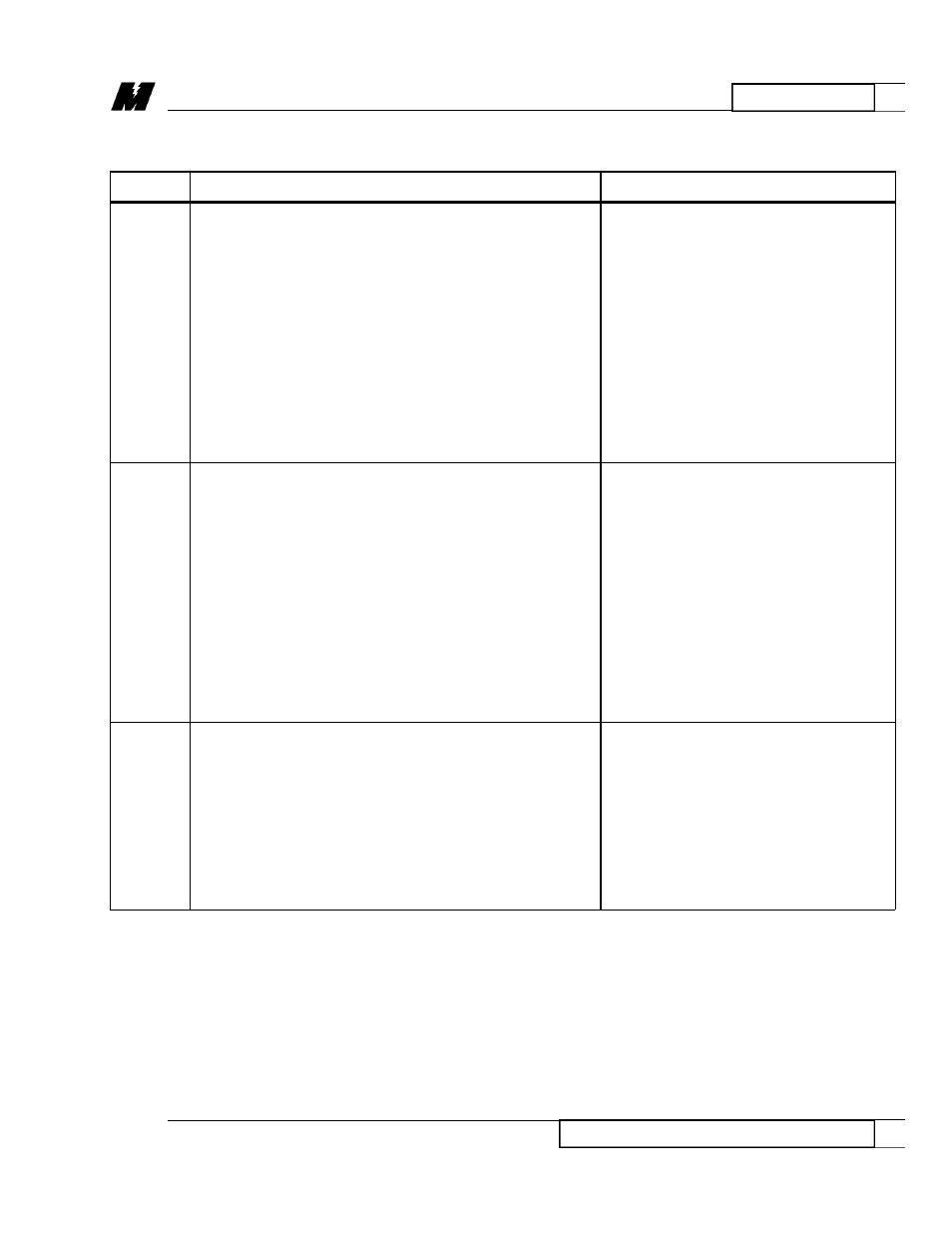
ELOA
When the PLC Gateway receives a logical output
allocation message from the DSD LAN, this error
message could appear for any of the following
reasons:
1. The internal allocation table is full and cannot
handle another allocation. The allocation table
has room for 1024 allocations. A logical
allocation uses 1 element in the table.
2. The bits specified in the allocation message
overlap with bits already allocated by
another node.
3. The bits specified by the allocation message
are not exactly the same as the bits already
allocated by this node.
EMMA
This indicates a mis-match during allocation.
Check the configuration in the
Texas Instruments PLC. For the base
When the PLC Gateway receives an allocation
and slot specified in the allocation
message (0x10, 0x11, 0x12, 0x13, or 0x2D) from the
message, the following modules are
network, it decodes the channel number into a base
expected in the allocation message:
and slot number and then requests through the
5136-TI card the configuration for that base from
0x10 -LOGO- 16X, 16 point
the Texas Instruments PLC. Once the configuration
Discrete Input Module
has been received, the gateway checks to make sure
0x11 -NUMO- 8WX, 8 channel
that the module in that slot is the correct one. If
Register Input Module
not, then this message appears and an error
0x12 -LOGI- 16Y, 16 point
message is sent to the node that issued the
Discrete Output Module
allocation message.
0x13 -NUMI- 8WY, 8 channel
Register Output Module
ENIA
When the PLC Gateway receives a numeric input
allocation message, this error message could appear
for one of the following reasons:
1. The internal allocation table is full and
cannot handle another allocation. The
table has room for 1024 allocations. A
numeric allocation uses 8 elements in
the table.
2. The sub channel is out of range. It can
range from 1 to 8.
Table 7. PLC Gateway Display Messages (Continued)
MESSAGE
DESCRIPTION
TROUBLESHOOTING
RD 3056-10