Braking circuit – Yaskawa GPD 506/P5 Section One User Manual
Page 31
PP.P5G5.01.Troubleshoot
Page 31
Rev. 06/11/2003
Braking Circuit
For 230V 0.4 kW-7.5kW models, 460V 0.4kW-15kW models and 600V 1.5kW-22kW models
Test Equipment - Analog Ohmmeter Set to R X 1 Scale
or Digital Multimeter set to the Diode Check.
The braking transistor is located in the main circuit and works in conjunction with
the braking resistor option installed to terminals B1 and B2. The transistor turns on
when the DC bus voltage reaches 380VDC for 230V models, 760VDC for 460V
models and 990VDC for 600V models. The transistor can be checked by following
the steps below. The most common failure is for the transistor to be shorted
between the collector and emitter. Readings will vary depending on inverter size.
Step No.
Ohmmeter Positive Lead
Ohmmeter Negative Lead
1
2
3
4
5
6
Connect to B2 terminal
Connect to the Emitter
Connect to the Emitter
Connect to B2 terminal
Connect to the Gate
Connect to the Gate
Connect to the Emitter
Connect to the Emitter
Connect to B2 terminal
Connect to B2 terminal
Connect to the Gate
Connect to the Gate
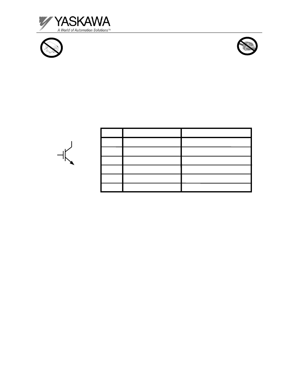
Braking Transistor Check
IGBT
Collector
Gate
Emitter