Input diodes – Yaskawa GPD 506/P5 Section One User Manual
Page 14
PP.P5G5.01.Troubleshoot
Page 14
Rev. 06/11/2003
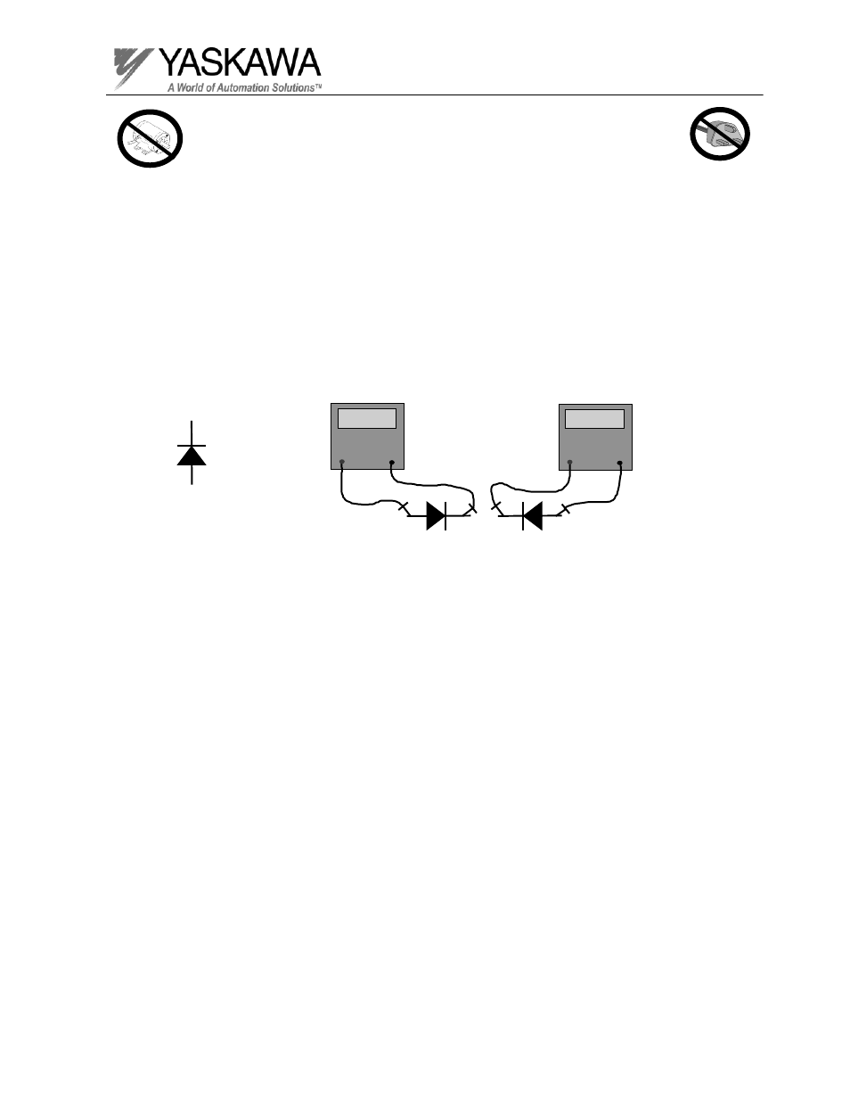
Input Diodes
The individual diodes that form the three-phase input rectifier bridge can easily be
checked by measuring the forward and reverse resistance of the diodes. Simply use
an analog or digital meter and measure the resistance across each diode. Refer to
the elementary diagram to determine the relationship between the main input
terminals (L1, L2, L3) and the DC bus terminals. By checking the resistance from
each input terminal to the positive bus and the negative bus (then swapping your
meter leads) you can check each of the diodes. Remember, you should see a
resistance reading typical of a diode, with low resistance in one direction and fairly
high resistance after you swap the meter leads.
Anode (+)
Cathode (-)
Resistance Readings
DVM
0.5
_
+
DVM
OL
_
+