Analog output option card ao-08 or ao-12 – Yaskawa AO-08 User Manual
Page 4
Yaskawa Electric America, Inc. – www.drives.com
IG.AFD.51, Page 4 of 4
Date: 07/01/04, Rev: 04-07
Analog Output Option Card
AO-08 or AO-12
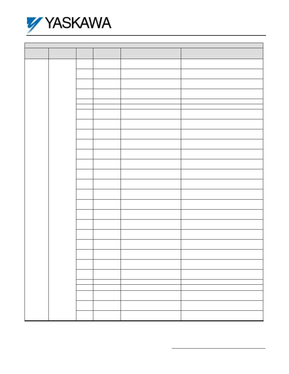
Table 5. Selecting the Monitored Output (F7/G7)
Terminal
Parameter
Set
Value
Control
Method
(1)
Output Monitor
Scaling
1 0,1,2,3,4 Frequency Reference
10V: Maximum output frequency
(0 ~ ± 10V possible)
2 0,1,2,3,4
Output Frequency
10V: Maximum output frequency
(0 ~ ± 10V possible)
3 0,1,2,3,4
Output Current
10V: Drive rated output current
(0 ~ 10V, absolute value)
5 1,2,3,4
Motor
Speed
10V: Maximum output frequency
(0 ~ ± 10V possible)
6 0,1,2,3,4
Output
Voltage
10V: 200VAC (400VAC)
7
0,1,2,3,4
DC Bus Voltage
10V: 400VDC (800VDC)
8 0,1,2,3,4
Output
Power
10V: Drive capacity kW
(0 ~ ± 10V possible)
9 2,3,4
Torque
Reference
10V: Motor rated torque
(0 ~ ± 10V possible)
15 0,1,2,3,4
Terminal A1 Input
10V: 100% (at 10V input)
(0 ~ ± 10V possible)
16 0,1,2,3,4
Terminal A2 Input
10V: 100% (at 10V input)
(0 ~ ± 10V possible)
17 0,1,2,3,4
Terminal A3 Input
10V: 100% (at 10V input)
(0 ~ ± 10V possible)
18 0,1,2,3,4
Motor
Secondary Current (Iq)
10V: Motor rated secondary current
(0 ~ ± 10V possible)
19
2,3,4
Motor Excitation Current (Id)
10V: Motor rated secondary current
(0 ~ ± 10V possible)
20 0,1,2,3,4
Output Frequency after
Soft-Starter (SFS)
10V: Maximum output frequency
(0 ~ ± 10V possible)
21 1,3,4
ASR
Input
10V: Maximum output frequency
(0 ~ ± 10V possible)
22 1,3,4
ASR
Output
10V: Motor rated secondary current
(0 ~ ± 10V possible)
24 0,1,2,3,4
PID
Feedback
10V: Maximum output frequency
(0 ~ ± 10V possible)
26 2,3,4
Output Voltage Reference
(Vq)
10V: 200VAC (400VAC)
(0 ~ ± 10V possible)
27 2,3,4
Output Voltage Reference
(Vd)
10V: 200VAC (400VAC)
(0 ~ ± 10V possible)
32
2,3,4
ACR (q) Output
10V: 100%
(0 ~ ± 10V possible)
33
2,3,4
ACR (d) Output
10V: 100%
(0 ~ ± 10V possible)
36 0,1,2,3,4
PID Input (Error)
10V: 100%
(0 ~ ± 10V possible)
37 0,1,2,3,4
PID Output
10V: Maximum output frequency
(0 ~ ± 10V possible)
38 0,1,2,3,4
PID
Setpoint
10V: Maximum output frequency
42
(2)
4
Estimated Motor Flux
10V: Rated motor flux
43
(2)
4
Motor Flux Current
Compensation
10V: Motor rated secondary current
(0 ~ ± 10V possible)
44
3,4
ASR Output without Filter
10V: Motor rated secondary current
(0 ~ ± 10V possible)
TD1
or
TD2
F4-01
or
F4-03
45 3,4
Feed Forward Control
Output
10V: Motor rated secondary current
(0 ~ ± 10V possible)
(1) Output available only when using one of the listed control methods (A1-02 setting):
0: V/Hz, 1: V/Hz with Encoder (PG), 2: Open Loop Vector, 3: Closed Loop Flux vector, 4: Open Loop Vector 2
(2)
(2) G7 only.