Servo on latch circuit – Yaskawa NS300 User Manual
Page 13
Subject: Technical Note
Product: NS300/NS500
Doc#: EM.MCD.05.106
Title: NS300/500 Master Ladder Example
Doc#: Copyright Yaskawa Electric America
©2004
May 9, 2007
Page 13
of 16
Additional Topics
In addition to the three main topics described above, a handful of specifics in the program are worth noting. Here
is a list of these items:
Servo-on latch circuit
Bit/byte manipulation for response/command codes in output bytes 0-1
Working registers and selecting the proper data to place in output bytes 2-3
Using MOD_R to load data with set/read commands
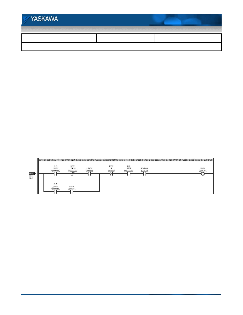
Servo on latch circuit
The servo on latch circuit is shown below. SVON can be enabled when the NS300/500 is not indicating an
emergency stop, the PLC_ESTP bit is set, and main power is applied to the servo amplifier. The coil is set on the
rising edge of the PLC_SVON bit. Note that the READY bit response from the NS300/500 must be active on the
rising edge of the PLC_SVON bit. The READY bit is only included in setting the coil, but does not participate in
latching the SVON coil. This setup is required as the READY bit changes state during the execution of the SVON
command. Once the coil is set, it is unlatched either by clearing the PLC_SVON command, by an emergency
stop occurring in either the PLC or the NS300/500, or if main power is removed from the servo.
Fig 10. Servo On Latch Circuit
Bit/byte manipulation for response/command codes in output bytes 0-1
Bit and byte manipulation is required when loading the response and command codes into output bytes 0-1. This
is necessary as the controller used in the example works in bit or word data types, and output bytes 0-1 use bit
and nibble data types for the associated commands. The flowchart on the following page describes this process.
Included with the flowchart are contents of the registers as the code is executed. Note: the first step of the
flowchart, loading the response code to MW00003, is completed by the user in other portions of the PLC code.