Freq. ref. unit, Analog speed reference model ds386 – Yaskawa DS386 User Manual
Page 4
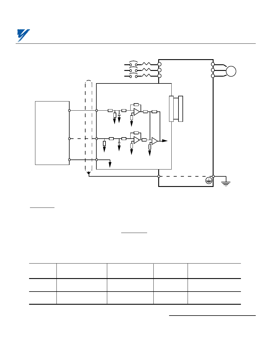
Table 3. Adjustments of Input Signal Gain and Bias for GPD 515/G5
GPD 515/G5
Function
Setting
Increment
Factory Setting
Parameter
Range
H3-02
Frequency command
0.0 to 1000.0%
0.1 %
10V/100.0%
gain (10V/xx%)
H3-03
Frequency command
-100 to 100%
1 %
0%
bias
Yaskawa Electric America, Inc . www.drives.com
02Y00025-0295 Page 4 OF 5
REL. 02/8/91
7. Adjustments. There are no adjustments to be made on the Analog Speed Reference option; however, the
drive will have to be reprogrammed for the input requirement of the remote device.
A. GPD 515/G5: See Table 3 and Figure 4.
IMPORTANT
For the Analog Speed Reference circuit to function properly, parameter b1-01
must be set to " 3 " (input to AI-14U replaces auto speed reference signal).
Figure 3. Interconnection for Analog Speed Reference (AI-14U) Circuit
2CN
2CN
TC1
12
GPD
515
or
GPD
503
AI-14U BOARD
L1
L2
L3
T1
T2
T3
E
2uF
20K ohm
0V
I M
MOTOR
MCCB
SHIELD
0V
0-10V
4-20mA
0V
FREQ. REF.
UNIT *
* USE HIGH ACCURACY VOLTAGE
REGULATOR FOR FREQ. REF. UNIT
250 ohm
10K ohm
10K ohm
2uF
20K ohm
10K ohm
TC2
TC3
(GPD 503)
(GPD 515)
ANALOG SPEED REFERENCE
MODEL DS386
- Tag Generator (30 pages)
- MP3300iec (82 pages)
- 1000 Hz High Frequency (18 pages)
- 1000 Series (7 pages)
- PS-A10LB (39 pages)
- iQpump Micro User Manual (300 pages)
- 1000 Series Drive Option - Digital Input (30 pages)
- 1000 Series Drive Option - CANopen (39 pages)
- 1000 Series Drive Option - Analog Monitor (27 pages)
- 1000 Series Drive Option - CANopen Technical Manual (37 pages)
- 1000 Series Drive Option - CC-Link (38 pages)
- 1000 Series Drive Option - CC-Link Technical Manual (36 pages)
- 1000 Series Drive Option - DeviceNet (37 pages)
- 1000 Series Drive Option - DeviceNet Technical Manual (81 pages)
- 1000 Series Drive Option - MECHATROLINK-II (32 pages)
- 1000 Series Drive Option - Digital Output (31 pages)
- 1000 Series Drive Option - MECHATROLINK-II Technical Manual (41 pages)
- 1000 Series Drive Option - Profibus-DP (35 pages)
- AC Drive 1000-Series Option PG-RT3 Motor (36 pages)
- Z1000U HVAC MATRIX Drive Quick Start (378 pages)
- 1000 Series Operator Mounting Kit NEMA Type 4X (20 pages)
- 1000 Series Drive Option - Profibus-DP Technical Manual (44 pages)
- CopyUnitManager (38 pages)
- 1000 Series Option - JVOP-182 Remote LED (58 pages)
- 1000 Series Option - PG-X3 Line Driver (31 pages)
- SI-EN3 Technical Manual (68 pages)
- JVOP-181 (22 pages)
- JVOP-181 USB Copy Unit (2 pages)
- SI-EN3 (54 pages)
- SI-ET3 (49 pages)
- MECHATROLINK-III (35 pages)
- EtherNet/IP (50 pages)
- SI-EM3 (51 pages)
- 1000-Series Option PG-E3 Motor Encoder Feedback (33 pages)
- 1000-Series Option SI-EP3 PROFINET (56 pages)
- PROFINET (62 pages)
- AC Drive 1000-Series Option PG-RT3 Motor (45 pages)
- SI-EP3 PROFINET Technical Manual (53 pages)
- A1000 Drive Option - BACnet MS/TP (48 pages)
- 120 Series I/O Modules (308 pages)
- A1000 12-Pulse (92 pages)
- A1000 Drive Software Technical Manual (16 pages)
- A1000 Quick Start (2 pages)
- JUNMA Series AC SERVOMOTOR (1 page)
- A1000 Option DI-101 120 Vac Digital Input Option (24 pages)