Edit a devicenet node, Proceed to, For a devicenet network – Yaskawa Tag Generator User Manual
Page 13
u
Edit a DeviceNet Node
Follow this procedure to edit node settings for an DeviceNet node.
1.
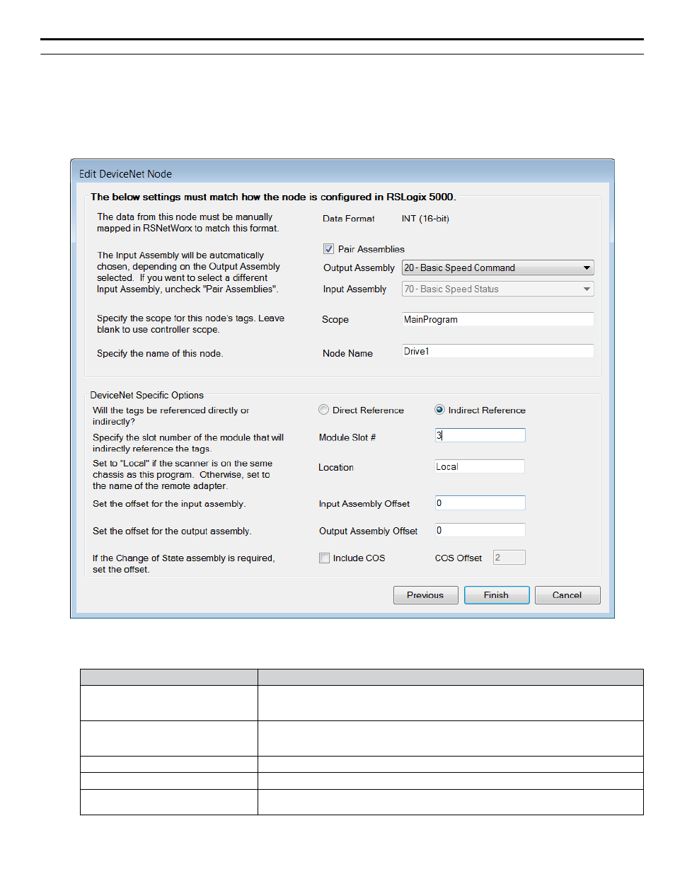
Match the fields in the "Edit DeviceNet/IP Node" dialog to the configuration in Logix Designer/RSLogix 5000 software.
Click the "Finish" button when all values are set.
NOTICE: NOTICE: Abnormal Equipment Operation. Match the fields in the "Edit DeviceNet Node" dialog to the configuration in
Logix Designer/RSLogix 5000 software. Invalid or mismatched tags may cause erroneous operation.
Figure 6 Edit DeviceNet Node Dialog
Table 3 Field Descriptions for the Edit DeviceNet Node Dialog
Dialog Field
Description
Data Format (Display only):
Field displays tag data size. The tags are created based on the data size displayed here.
This field is for display only and not configurable in the Tag Generator. The data in this display
field must be manually mapped in RSNetWorx.
Pair Assemblies (Checkbox):
Select this checkbox when using matching assemblies.
Example: Output Assembly 20 is typically paired with Input Assembly 70. Deselect this
checkbox to use differing assemblies.
Output Assembly (Drop-down list):
Select the desired Output Assembly.
Input Assembly (Drop-down list):
Select the desired Input Assembly when the “Pair Assemblies” checkbox is deselected.
Scope (Textbox):
Specify the scope for this node's tags. Leave blank to use the controller scope. The default
value for this field is “MainProgram”.
4 EtherNet/IP or DeviceNet Projects
YASKAWA TOEP YAICOM 20A Tag Generator User Guide
13