SMA SIC-PB User Manual
Page 8
SMA Solar Technology AG
Installation Guide
3/4
SIC-PB-IEN083510
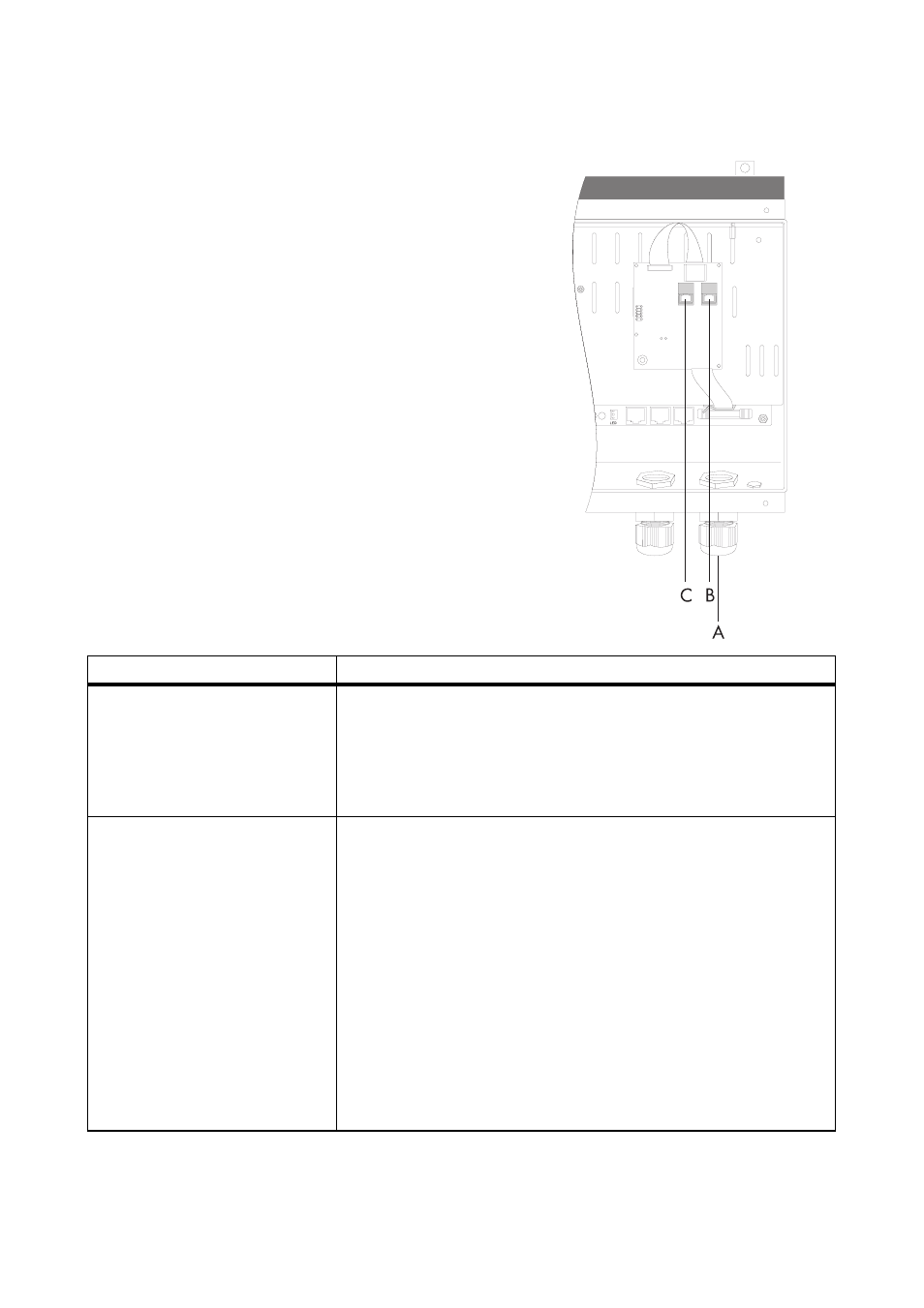
Electrical Connection
1. Remove the metric-thread cable screw
connectionslocknut(A)andslideitoverthecommunica
tioninterfacecable(RJ45cableprovided).'
2. Remove the seal insert from the cable screw
connection and remove the dummy plug.
3. Route the communication interface cable through a
cable opening in the seal insert.
4. Insert the seal insert along with the communication
interface cable into the cable screw connection.
5. Route the communication interface cable through
the cable screw connection into the inside of the
Sunny Island Charger and insert it into a RJ45
socket (B) of the communication interface.
6. Insert a termination connector into the open RJ45
socket (C) of the communication interface.
If...
Then...
one Sunny Island Charger is
connected to the system...
1. Route the communication interface cable of the Sunny Island
Charger to the Sunny Island and insert it into the
"ComSyncIn" socket/"Sync IN" socket in the Sunny Island.
2. Insert a termination connector in the "ComSyncOut" socket/
"SyncOUT" socket in the Sunny Island.
several Sunny Island Chargers
are connected to the system...
1. Route the communication interface cable from the first Sunny
Island Charger to the next Sunny Island Charger (in this
case, the second Sunny Island Charger) and insert it into a
RJ45 socket of the communication interface.
2. Follow the same procedure for the first two Sunny Island
Charger devices to connect additional Sunny Island
Charger devices.
3. Route the communication interface cable from the last Sunny
Island Charger to the Sunny Island and insert it into the
"ComSyncIn" socket/"Sync IN" socket in the Sunny Island.
4. Insert a termination connector in the "ComSyncOut" socket/
"SyncOUT" socket in the Sunny Island.