Echo 99944200490 User Manual
Page 8
8
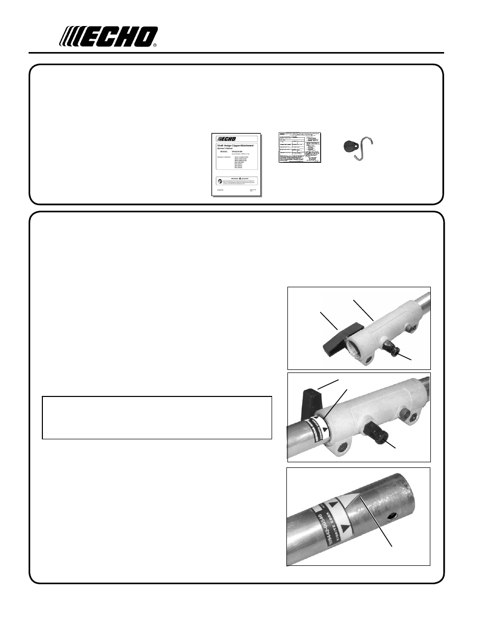
1. Set Power Head/Shaft Assembly on a level surface.
2. Pull locator pin (A) and rotate counter clockwise 1/4 turn to lock
out position.
3. Remove vinyl cap from attachment drive shaft.
4. Remove cardboard spacer, if necessary.
5. Carefully fit attachment lower drive shaft assembly into coupler (B)
to decal assembly line (C), making sure that the inner lower drive
shaft engages into the upper drive shaft mount.
Parts Required: PAS or SRM-SB Power Head w/Shaft & Coupling.
c
ontents
The ECHO product you have purchased has been factory pre-assembled for your convenience.
After opening the carton, check for damage. Immediately notify your retailer or ECHO Dealer of damaged or missing
parts. Use the contents list to check for missing parts.
_____ 1 - Power Blower Attachment
_____ 1 - Operators Manual
_____ 1 - Warranty Card
_____ 1 - Storage Hook Assembly
a
ssembly
power
head
shaft
/
lower
shaft
assembly
C
E
D
6. Rotate locator pin (A) 1/4 turn clockwise to engage lower shaft
hole. Insure locator pin is fully engaged by gently twisting
lower drive shaft. Locator pin (A) should snap flush in coupler.
Full engagement will prevent further shaft rotation.
7. Secure lower shaft assembly to coupler by tightening clamping
knob (D).
NOTE
Earlier model Power Heads may have shorter couplings. Short
couplings fit flush to decal point (E). New couplings are 4-3/4 in.
long, and fit flush to line (C).
A
A
B
D