Mt 25 x, Mt 12 x, Mt 12 p mt 25 p – HEIDENHAIN MT 12 User Manual
Page 2: Mt 25 p, Mt 12 p
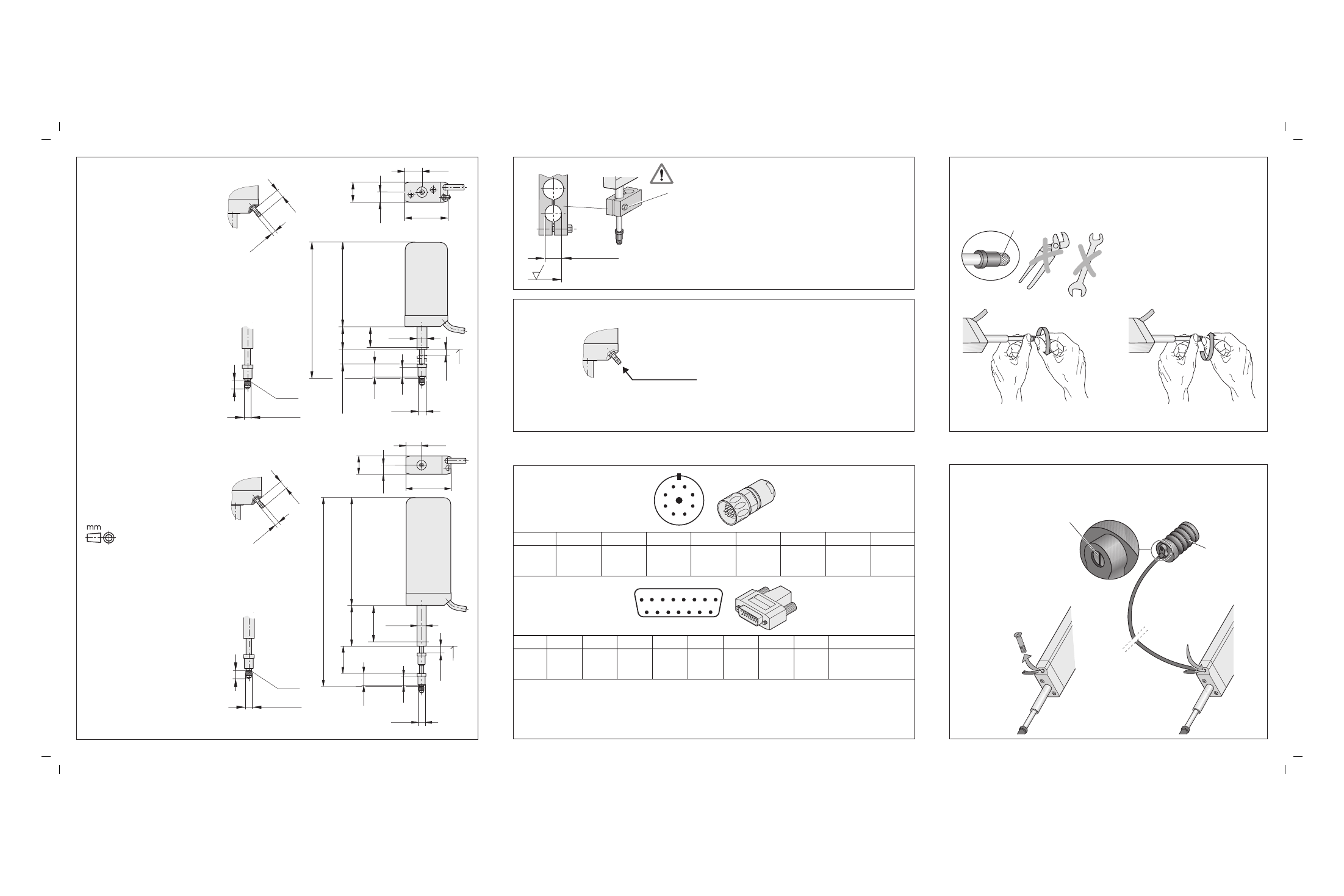
À = Luftanschluß (für 2 mm Schlauch)
Air connection (for 2 mm tube)
Raccordement dair (pour tuyau de 2 mm)
Attacco dellaria (protezione per 2 mm)
Conexión de aire (para manguera de 2 mm)
r = Referenzmarken-Lage
Reference mark position
Marque de référence
Indici di riferimento
Marca de referencia
MT 25 x
Messeinsatz wechseln
Changing the measuring contact
Changer de touche de mesure
Cambiare dispositivo di misura
Cambiar punta de medida
Handfest anziehen
Tighten the screw finger-tight
Serrer à la main
Stringere a mano
Apretar fuertemente con la mano
M
d
= 0.1 Nm
1.
2.
Ausfahrgeschwindigkeit einstellbar
Extension speed of plunger is adjustable
Vitesse de sortie réglable
Velocità di uscita regolabile
Velocidad de salida ajustable
Option
Option
Option
Opzioni
Opciones
ID 257 790-01
Anschlussbelegung
Pin Layout
Raccordements
Piedinatura
Distribución del conector
Innenschirm
Internal shield
Blindage interne
Schermo interno
Blindaje interno
1)
Kabelschirm mit Gehäuse verbunden
Cable shield connected to housing
Blindage du câble relié au boîtier
Collegare lo schermo del cavo alla carcassa
Pantalla del cable conectada a carcasa
7
6
5
4
2
8
9
3
1
1
9
2
10
3
5
4
6
8
7
11 12 13 14 15
3
9
4
5 V
U
P
0 V
U
N
1)
I
1
+
2
1
5
7
6
8
I
1
I
2
+
I
2
I
0
+
I
0
5, 8, 10, 12, 13, 15
/
4
6
2
5 V
U
P
0 V
U
N
1)
I
1
+
9
1
3
14
11
7
I
1
I
2
+
I
2
I
0
+
I
0
¬ 8H7 mm
0.8
Vorsicht: Zu starke Kraft klemmt Meßbolzen
Attention: Excessive force jams the plunger
Attention: Force trop élevée serre la tige de mesure
Attenzione: Una forza eccessiva blocca lo stelo di misura
Atención: Una fuerza excesiva bloquea el vástago de medición
p = 0.55 ... 1.2 bar
MT 12 P
MT 25 P
tab 2: class 1
tab 3: class 4
tab 4: class 1
ISO 8573-1: 1995
MT 12 x
MT 12 x
Tolerancing ISO 8015
ISO 2768 - m H
< 6 mm: ±0.2 mm
Á = Klemmbereich
Clamping area
Zone de serrage
Zona di bloccaggio
Area de fijación
MT 25 P
À
¬ 3.2
6.5
r
¬ 4.5+0.6
M2.5
6
5.5±1
ML 25.6+0.5
31.5
99.5
16
5
¬ 8h6
¬ 6.5
8.1
10.1
14.9
42.2
8.6
17.2
26.5
Á
MT 12 P
À
¬ 3.2
6.5
r
ML 12.6+0.2
17.5
70
111
¬ 8h6
¬ 6.5
8.1
10.1
14.3
35.8
8.6
17.2
5.5±1
¬ 4.5+0.6
M2.5
6
15
Á