Grass Valley TTN-PS-FR User Manual
Page 13
PS-FR
Rev. 1
7
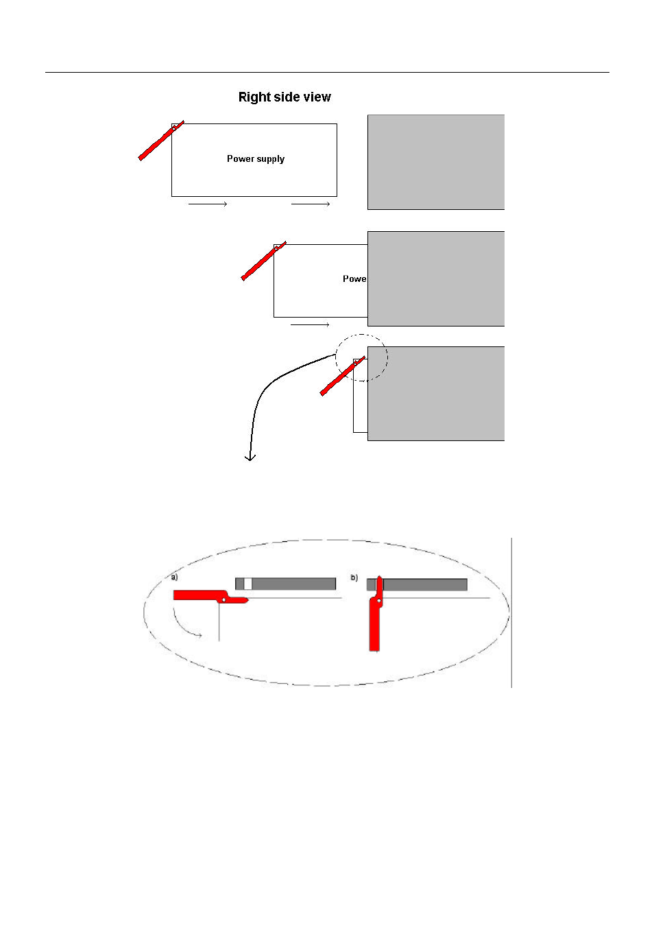
Figure 4: Inserting power supplies
Slide the card into the plastic guide rails inside the sub-rack until the red handle is close to the sub-rack
front. A detailed description of the last part of the insertion process is shown in figure 5.
Figure 5: Inserting power supplies (continued)
On the top of the rack is a hole above each module slot. When the tip of the handle is just below this hole
(fig. 5a)), start to bend the handle downwards as in figure 5. The tip of the handle enters the hole and the
card is locked and proper contact ensured when the handle is in upright position (figure 5b)).
4.3
Adding new power supply modules
If the frame is not fully equipped with 4 power supply modules, a new module can be added.
This is done by replacing the blank cover found on the rear with a power supply module as shown in
figure 1. The module is mounted with 4 M2.5x8 screws with a pozidrive screwdriver (PZ1).
- LDK 5302 (24 pages)
- SFP Optical Converters (18 pages)
- 2000GEN (22 pages)
- 2011RDA (28 pages)
- 2010RDA-16 (28 pages)
- 2000NET v3.2.2 (72 pages)
- 2000NET v3.1 (68 pages)
- 2020DAC D-To-A (30 pages)
- 2000NET v4.0.0 (92 pages)
- 2020ADC A-To-D (32 pages)
- 2030RDA (36 pages)
- 2031RDA-SM (38 pages)
- 2041EDA (20 pages)
- 2040RDA (24 pages)
- 2041RDA (24 pages)
- 2042EDA (26 pages)
- 2090MDC (30 pages)
- 2040RDA-FR (52 pages)
- LDK 4021 (22 pages)
- 3DX-3901 (38 pages)
- LDK 4420 (82 pages)
- LDK 5307 (40 pages)
- Maestro Master Control Installation v.1.5.1 (455 pages)
- Maestro Master Control Installation v.1.5.1 (428 pages)
- 7600REF Installation (16 pages)
- 7600REF (84 pages)
- 8900FSS (18 pages)
- 8900GEN-SM (50 pages)
- 8900NET v.4.3.0 (108 pages)
- Safety Summary (17 pages)
- 8900NET v.4.0.0 (94 pages)
- 8906 (34 pages)
- 8911 (16 pages)
- 8900NET v.3.2.2 (78 pages)
- 8914 (18 pages)
- 8912RDA-D (20 pages)
- 8916 (26 pages)
- 8910ADA-SR (58 pages)
- 8920ADC v.2.0 (28 pages)
- 8920ADC v.2.0.1A (40 pages)
- 8920DAC (28 pages)
- 8920DMX (30 pages)
- 8920ADT (36 pages)
- 8920MUX (50 pages)
- 8921ADT (58 pages)