Grass Valley TTN-PS-FR User Manual
Page 11
PS-FR
Rev. 1
5
3 GPI Module status outputs
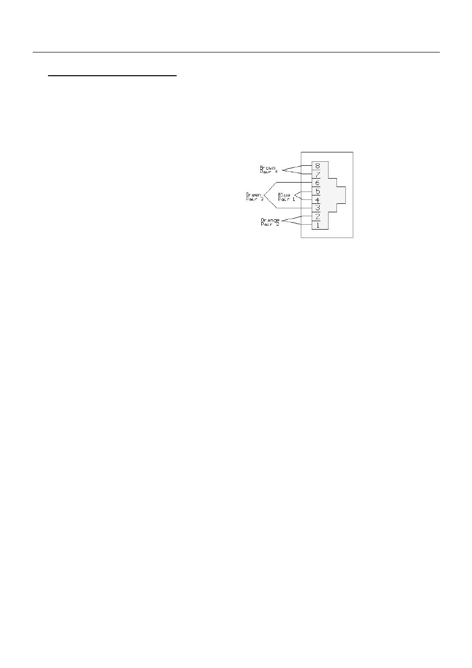
The GPI module status outputs can be used for wiring up alarms for third party control systems. Each
back plane is equipped with an RJ-45 connector for GPI status from both power supply modules, as
shown in figure 2. The status is a copy of the signal shown on the LED in front of the power module.
There are two module status output pins per power supply. Relay 1A and relay 1B are for power supply 1,
whereas relay 2A and relay 2B are for power supply 2.
Pin 1
Relay 1A
Pin 2
Relay 1B
Pin 3
Relay 2A
Pin 4
Relay 2B
Pin 5
Not Connected
Pin 6
Not Connected
Pin 7
Not Connected
Pin 8
Not Connected
Fig. 2 GPI outlet (RJ-45)
In case of power failure, outputs A and B will be physically connected (low impedance), otherwise the
connection between outputs A and B will be high impedance.
- LDK 5302 (24 pages)
- SFP Optical Converters (18 pages)
- 2000GEN (22 pages)
- 2011RDA (28 pages)
- 2010RDA-16 (28 pages)
- 2000NET v3.2.2 (72 pages)
- 2000NET v3.1 (68 pages)
- 2020DAC D-To-A (30 pages)
- 2000NET v4.0.0 (92 pages)
- 2020ADC A-To-D (32 pages)
- 2030RDA (36 pages)
- 2031RDA-SM (38 pages)
- 2041EDA (20 pages)
- 2040RDA (24 pages)
- 2041RDA (24 pages)
- 2042EDA (26 pages)
- 2090MDC (30 pages)
- 2040RDA-FR (52 pages)
- LDK 4021 (22 pages)
- 3DX-3901 (38 pages)
- LDK 4420 (82 pages)
- LDK 5307 (40 pages)
- Maestro Master Control Installation v.1.5.1 (455 pages)
- Maestro Master Control Installation v.1.5.1 (428 pages)
- 7600REF Installation (16 pages)
- 7600REF (84 pages)
- 8900FSS (18 pages)
- 8900GEN-SM (50 pages)
- 8900NET v.4.3.0 (108 pages)
- Safety Summary (17 pages)
- 8900NET v.4.0.0 (94 pages)
- 8906 (34 pages)
- 8911 (16 pages)
- 8900NET v.3.2.2 (78 pages)
- 8914 (18 pages)
- 8912RDA-D (20 pages)
- 8916 (26 pages)
- 8910ADA-SR (58 pages)
- 8920ADC v.2.0 (28 pages)
- 8920ADC v.2.0.1A (40 pages)
- 8920DAC (28 pages)
- 8920DMX (30 pages)
- 8920ADT (36 pages)
- 8920MUX (50 pages)
- 8921ADT (58 pages)