4 power module insertion – Grass Valley TTN-PS-FR User Manual
Page 12
PS-FR
Rev. 1
6
4 Power Module insertion
In order to reconfigure or expand the number of power modules within a rack, the front panel must be
removed. Each power module has a corresponding connector module at the rear, and is hot swappable.
4.1 Opening the front panel
The front panel is hinged in the bottom. Release the three screws in the top in order to get access to the
power modules inside. In order to detach the front panel completely, an opening angle of 135° is needed.
Pull the panel gently to the left while holding the front panel in the 135° position. Revert the process in
order to mount the front panel again. It is not necessary for normal maintenance to remove the front panel
completely.
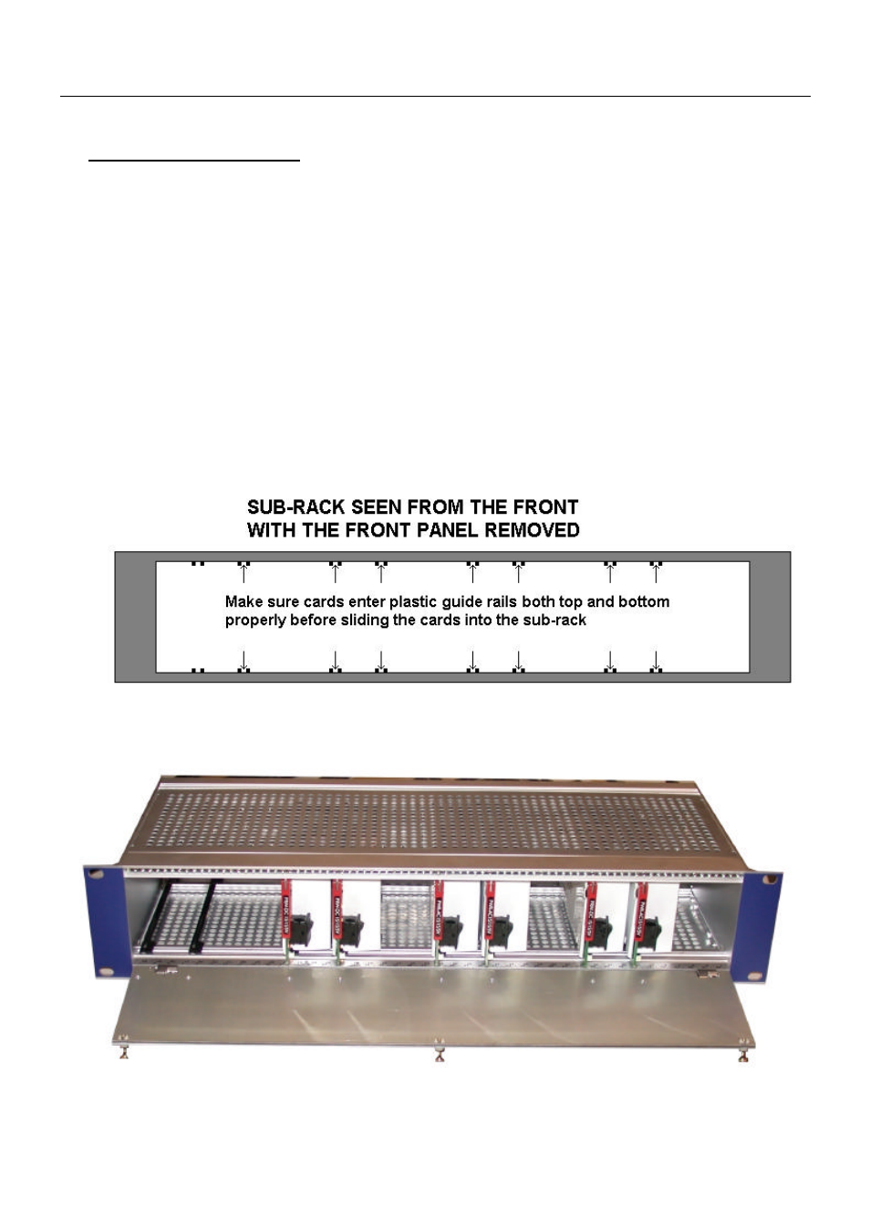
4.2 Power supply insertion
After the front panel is opened, full access to the power supplies inside the sub-rack is given as shown in
figures 3a and 3b.
Figure 3a: The sub-racks are equipped with plastic guide rails to align the module cards into their
respective position).
Figure 3b:Picture of the PS-FR with the front panel opened.