Area a – sdi/data in area b – sdi/data out, Area a – sdi/data in, Area b – sdi/data out – Grass Valley Telethon 3G User Manual
Page 15
11
Telethon 3G
User Guide
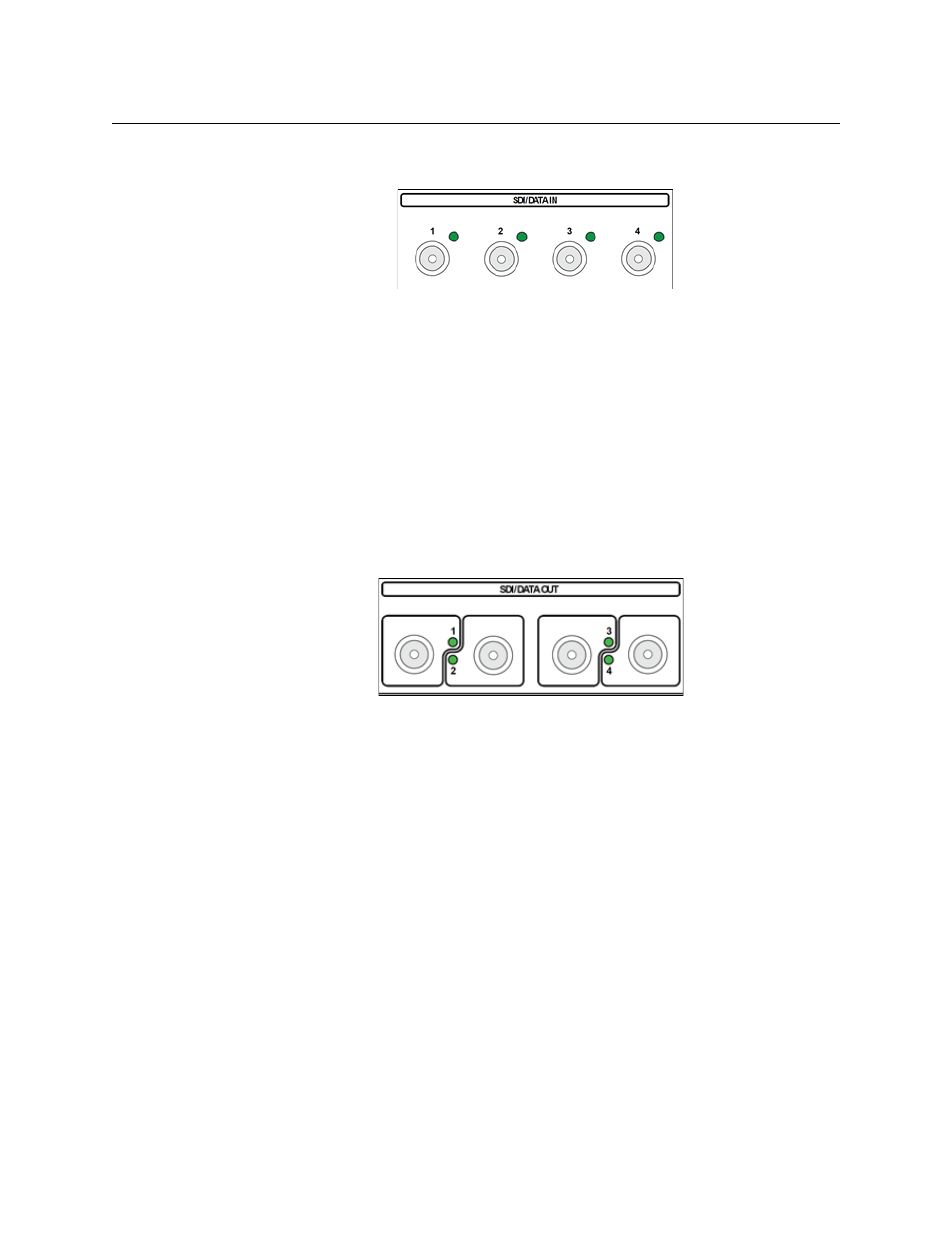
Area A – SDI/DATA IN
Fig. 3-3: Four SDI/DATA In BNC Connectors
The Telethon 3G has four SDI/DATA In BNC Connectors. All four inputs operate identically
and are multiplexed for transmission on the fiber output of the unit for demultiplexing to
the four SDI outputs on the receiving unit.
The SDI/DATA connections can carry a variety of Baseband and Data type signals (see
Each input has an LED monitor that indicates the following:
• Green: SDI signal is present
• Unlit : nothing is connected
Area B – SDI/DATA OUT
Fig. 3-4: Four Fiber SDI/DATA Output BNCConnectors
The Telethon 3G has four SDI/DATA Output BNC Connectors. All four Outputs operate
identically and are multiplexed for transmission on the fiber output of the unit.
Each output has an LED monitor that indicates the following:
• Green: the Telethon 3G is receiving a signal for the indicated channel over the
Multiplexed Fiber Optic Cable and SDI signal is present
• Alternating between Red and Green: a Fiber Optic connection is detected for the
indicated channel, but no SDI is present.
• Red: no optical connection is detected or the active optical signal has fallen below
-22 dBm
See
on page 12 for more information on understanding dBm
measurements.