Hdx faceplate indicators – Grass Valley SHED Jul 25 2014 User Manual
Page 17
13
SHED and HDX
User Guide
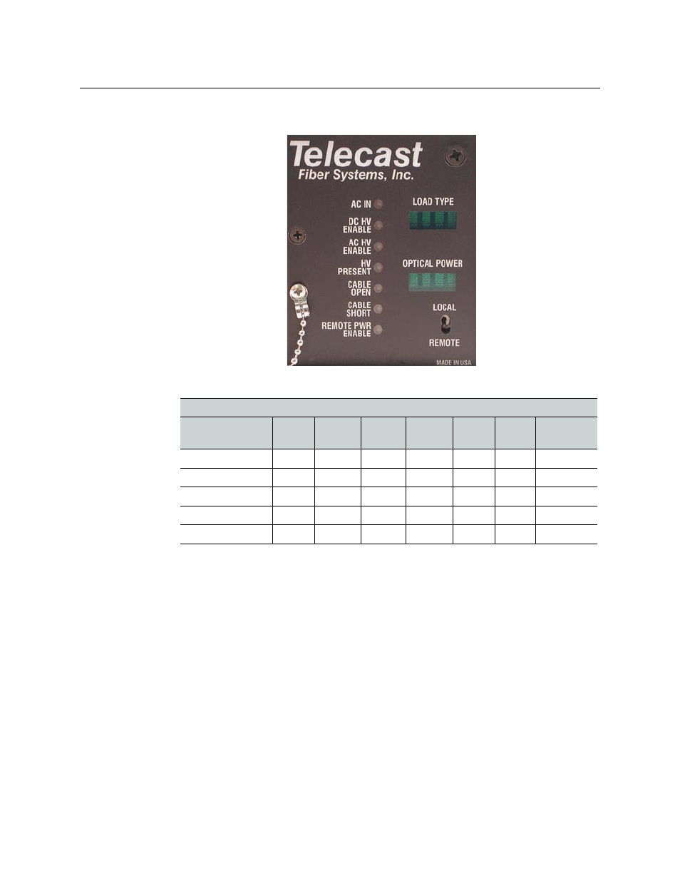
HDX Faceplate Indicators
Fig. 3-1: HDX Front Panel Displays
In both active and passive systems, the camera CCU needs to be powered on first and the
camera head needs to be in the ON position. In passive systems, once local power is applied
to the camera, the system should work normally. In active systems, the HDX will take a few
seconds to:
• determine what kind of equipment is attached
• safely apply the correct voltage for that equipment
LED indicators (see
and the HDX LED Indicators table above) will show
diagnostic information. An Open or Shorted hybrid cable will always result in a fault
condition. The remainder of the LEDs will be Green or Out depending on what type of
camera (or Power Plus) is attached to the HDX (see the HDX LED Indicators table above).
Incoming optical power is indicated on the lower 4-segment display on the HDX. -20 dBm is
the least amount of optical power that can reliably keep the system functioning. If the CCU
is operating normally (typical optical output of approx. -7 dBm) and the HDX is showing
high loss, check your installed cable for bend radius and connector problems.
HDX LED Indicators
AC IN
DC HV
Enable
AC HV
Enable
HV
Present
Cable
Open
Cable
Short
Remote
Pwr Enable
Nothing attached
Green
Unlit
Unlit
Unlit
Red
Unlit
Unlit
PowerPlus
Green
Green
Unlit
Green
Unlit
Unlit
Unlit
Ikegami
Green
Unlit
Green
Green
Unlit
Unlit
Unlit
Sony 750
Green
Unlit
Green
Green
Unlit
Unlit
Unlit
Sony 950
Green
Unlit
Green
Green
Unlit
Unlit
Unlit