Cr series compact routers, Configuration, Ethernet connections – Grass Valley CR Series Quick Start v.3.2 User Manual
Page 8: Power and ground, Connections for 64×64 routers, Rotary switches
8
Product Number: QG0003-13 Revision: 3.2; Date: 02 Dec 14
CR Series Compact Routers
The AES routers require a reference to operate in synchronous
mode. SDI routers require a reference to perform switches in
accordance with SMPTE RP168.
The machine control routers do not have video reference connec-
tors.
In stand-alone networks, devices that send and receive sig-
nals on multiple levels should be connected to the same input
or output on all the routers that service those levels. Other-
wise, multi-level operations will produce unwanted results.
In a CRSC network, there is no such restriction. Connections
are made on the basis of router levels and panel design. (The
connections you will make are actually defined during panel
configuration.)
Making the connections for analog audio might require cus-
tom cabling (because of the DB25 connectors). Making the
connections for machine control routers might also require
custom cabling because most controlled “machines” use DE9
connectors.
Ethernet Connections
If you have a router network, connect the router to your
Ethernet switch using CAT5 Ethernet cable (with RJ-45 con-
nectors).
Similarly connect your remote panel modules to your Ether-
net switch.
Similarly connect your configuration PC to your Ethernet
switch if you intend to use CRSC (or NV9000-SE Utilities).
Power and Ground
Connect the grounding lug to earth ground. Use copper cable
from 14–6AWG. See figures 6, 7, or 8.
(There is no on-off switch. Each router requires at least one
power supply and one AC outlet for each power supply.)
Control panels receive power from the router or remote panel
module on which they are mounted.
For the 64×64 Routers
Use caution when connecting power. Each power supply pro-
vides 48VDC at over 3 A. The ring at the end of the connector
is ground. It is very easy to short power to the ring or to the
metal router frame. Therefore, always plug the power supply
connector into the router frame before you connect the
power supply to AC power.
For All Other Routers
Plug the 4-pin connectors of your power supplies into PS1 or
PS2, or both. Insert the AC plugs into an AC wall socket or
other source of AC power.
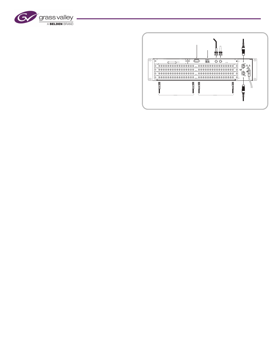
Connections for 64×64 Routers
The 64×64 routers (CR6464-3Gig and CR6464-AES) are mod-
ular in construction: they have 4 I/O card slots into which
you may insert up to 4 I/O cards.
The routers also have removable control cards and crosspoint
cards, and a removable fan unit. It should never be necessary
to remove these modules unless you are instructed to do so by
a Grass Valley technician.
The router switches AES audio if it is populated with one or
more AES cards. The router switches video if it is populated
with one or more 3Gig cards (the label on the front of the
router notwithstanding). You must not mix I/O cards in the
router frame. (The router is considered “unidentified” if it has
no I/O cards.)
As you face the rear of the router, its 64 inputs are in a group
at the left and its 64 outputs are in a group at the right. Con-
nect your I/O devices to the router using DIN 1.0/2.3 cables.
Make video reference, Ethernet, and automation connections
as described earlier.
Configuration
For many stand-alone routers with a control panel, or for a
stand-alone network of routers, there is very little to configure,
beyond setting the rotary switches. Machine control routers
are the exception: you must use CRSC to set the port types
according to the equipment you have connected to the ports.
For compact routers in a NV9000 system, the configuration is
defined in NV9000-SE Utilities. There are many options to
consider. Refer to your User’s Guide or contact Grass Valley
for information regarding router control systems or automa-
tion.
Rotary Switches
As directed under Installation, set each router’s 16-position
‘Frame ID’ rotary switch (on the front face of the router) to a
non-zero position. Also set each remote panel module’s
rotary switch as directed under Installation.
For CQX routers, also set the ‘Mode’ rotary switch as directed
under Installation.
Reference
Termination
Inputs (1–64)
Ethernet
Primary
Power
Automation
Redundant
Power
Video
Reference
GND
Outputs (1–64)
DIN1.0/2.3
DIN1.0/2.3
Figure 9. 64×64 Router connections