Cr series compact routers, Stand-alone cr6400 networks, Crsc networks – Grass Valley CR Series Quick Start v.3.2 User Manual
Page 5: Nv9000 router control system, Cqx system
Product Number: QG0003-13 Revision: 3.2; Date: 02 Dec 14
5
CR Series Compact Routers
Stand-Alone CR6400 Networks
You can create a network of up to four 64×64 routers, without
any remote panels. Each router may have a captive control
panel, although just one captive panel is sufficient.
The networked 64×64 routers function as a stand-alone net-
work. Each router in the network is considered a distinct
level. (CR6400 routers can also be used in CRSC networks.)
CRSC Networks
You may have up to 8 levels (but a maximum of 4 routers) and
up to 16 remote panel modules in a CRSC network.
You can have multiple independent CRSC networks. CRSC
can detect (and manage) them if your configuration PC has
suitable network connections. Multiple networks are then
called subnets. CRSC handles one subnet at a time.
Set the rotary switches as follows.
For routers, the rotary switch initially sets the router’s IP
address. For each router, choose a switch position from 1 to F:
Default level = switch setting.
Default Subnet address = switch setting + 100.
The default IP address is 192.168.2.address. Thus, default sub-
net addresses for routers range from 100 to 115. Each router’s
rotary switch setting must be unique in that range.
Once the routers are established on the network, you can use
CRSC software to override their IP addresses and assign levels,
eliminating the dependence on the rotary switch position.
The switch settings of remote panel modules must also be
distinct initially. For each remote panel module, choose a
switch position from 0 to F:
Default subnet address = switch setting + 50.
The default IP address is 192.168.2.address. Thus, subnet
addresses for remote panel modules range from 50 to 65.
You can use CRSC software to reassign the IP addresses of
remote panel modules too.
Routers and remote panels with switch position 0 will reset to the
factory default if power is removed.
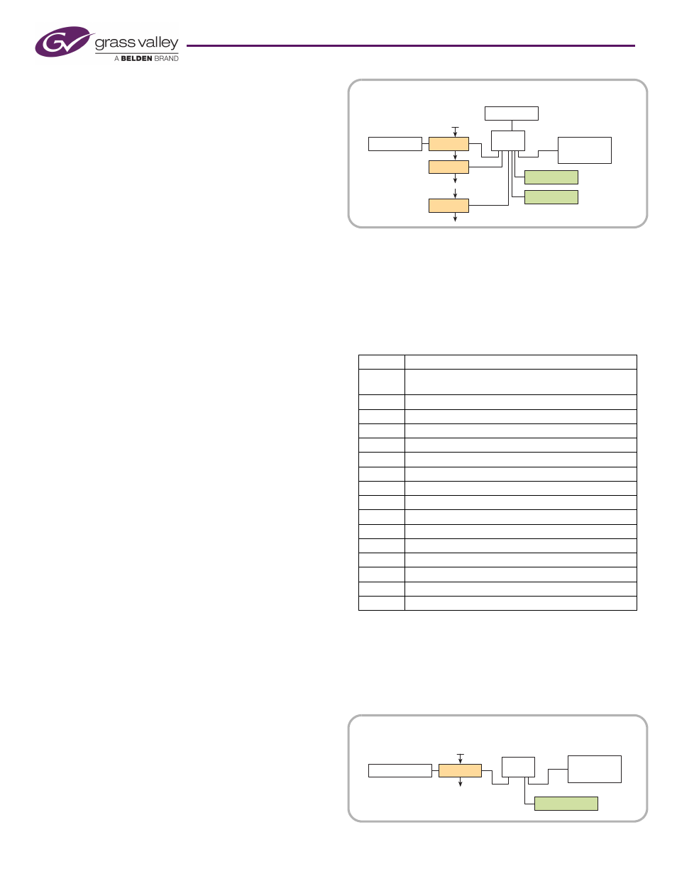
NV9000 Router Control System
You must also use CRSC to designate IP addresses for an
NV9000 router control system. Set up the IP addresses and
levels as you would for a CRSC network.
Then use CRSC to enable any remote panels for operation
under NV9000. It is recommended that you configure the
remote panels for DHCP.
The number of compact routers or remote panels in your
NV9000 system is limited only by throughput.
CQX System
A CQX router network is restricted to one CQX router. One
captive CQX panel or one remote CQX panel (or both) is
allowed. The network can be connected to a configuration PC
running CRSC.
You can create more than one CQX subnet.
Mode
CQX routers have a 16-position ‘Mode’ rotary switch that
governs the video rate of the router.
Set this switch according to the following table:
Frame ID
The 16-position Frame ID switch sets the router’s default IP
address. For any CQX router, choose a switch position from 1
to 4: Subnet address = switch setting + 200.
The default IP address is 192.168.2.address. Thus, subnet
addresses for routers range from 201 to 204.
Setting
Rate
0
1080i, 59.94 or 60; 1080p, 29.97 or 30;
1080psf, 29.97 or 30
1
1080i, 50; 1080p, 25; 1080psf, 25
2
525i, 59.94
3
625i, 50
4
720p, 59.94 or 60
5
720p, 50
6
1080p, 59.94 or 60
7
1080p, 50
8
2 × 1080i, 59.94 or 60
9
2 × 1080i, 50
A
720p, 29.97 or 30
B
720p, 25
C
720p, 23.98 or 24
D
1080p, 23.98 or 24; 1080psf, 23.98 or 24
E
reserved
F
reserved
Router
Ethernet
Switch
Config. PC
Remote Panel
Router
Router
Video Ref.
Remote Panel
Captive Panel
optional
optional
NV9000
Figure 3. NV9000 Router Network
CQX Router
Ethernet
Switch
Config. PC
Remote CQX Panel
Video Ref.
Captive CQX Panel
optional
Figure 4. CQX Router Network