Cr series compact routers, Rack mounting, Serial port – Grass Valley CR Series Quick Start v.3.2 User Manual
Page 7: I/o cables, video reference cable, Figure 6. router connections (bnc), Figure 7. router connections (db25), Figure 8. router connections (rj-45), Figure 5. rack mount
Product Number: QG0003-13 Revision: 3.2; Date: 02 Dec 14
7
CR Series Compact Routers
You can install button legends at this (or any) time. Button
legend templates are included on your CD. See Button Legends
on page 9.
Rack Mounting
Place the router (or router assembly) in the rack where you
want it, aligning the screw holes with holes in your rack
frame. Secure the router using your screws, nuts, and washers,
as required. See Figure 5.
Mount remote panel modules the same way.
For the 1RU routers (or remote panel modules), the mounting
holes are spaced 1.25″ (31.75mm) vertically and allow
approximately 1/8″ (3mm) of play horizontally.
For the 2RU routers (or remote panel modules), the 3 mount-
ing holes on each side are spaced 1.25″ (31.75mm) and 1.75″
(44.45 mm) (overall, 3.0″or 76.2 mm) vertically and also
allow approximately 1/8″ (3mm) of play horizontally.
Because the routers are small, you might not have enough space
to reach behind the router and make I/O connections. In that
case, make I/O connections first and save mounting until last.
Serial Port
If you intend to use the router under an external control sys-
tem, connect the 9-pin serial port to a serial port of your sys-
tem. The communication protocol is NVSP over RS-422 or RS-
485, at 38,400 Baud, for routers and is not available for
remote panel modules. Contact Grass Valley technical sup-
port for more information and to obtain the NVSP protocol
guide which is essential.
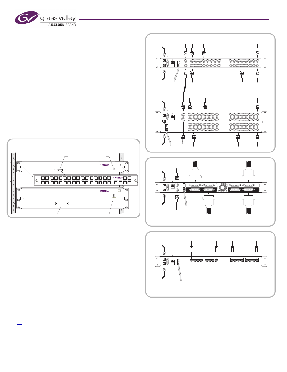
I/O Cables, Video Reference Cable
The 64×64 routers are of modular construction and have DIN
1.0/2.3 I/O connectors. Setup for the 64×64 routers is differ-
ent from the other routers. See
Connections for 64×64 Rout-
ers
, following.
The analog audio routers have DB25 connectors. The
machine control routers have RJ-45 connectors. The other
routers have BNC connector. See figures 6, 7, and 8.
If your routers are in an NV9000 router control system, the con-
figuration you create for your NV9000 system will include your
device connections.
Connect the video reference input. (Doing this is optional,
but recommended.) This connection is loop-through, non-
terminating. Be sure to terminate the output of the last con-
nector in the series with a 75Ω BNC terminator. See Figure 6.
I/O
I/O
Video
Ref
Reference
Termination
GND
Redundant
Power
Primary
Power
Ethernet
Automation
Ethernet
Primary
Power
Automation
I/O
I/O
GND
Redundant
Power
Figure 6. Router connections (BNC)
Inputs
Outputs
Video
Ref
GND
Redundant
Power
Primary
Power
Ethernet
Automation
Video
Ref
WC0053 or
equiv. cable
WC0053 or
equiv. cable
Figure 7. Router connections (DB25)
...Ports...
Redundant
Power
Primary
Power
Ethernet
Automation
...Ports...
GND
Figure 8. Router connections (RJ-45)
Digital Video Router
PS1
FRAME ID
PS2
CR1616-HD
Digital Audio Router
CR3232-AES
PS1
PS2
CP1616
Source
Dest
1
2
3
4
5
6
7
8
9
10
11
12
13
14
15
16
Control Panel
Connector
Rotary Switch
Connector Cover Plate
Rotary Switch
Figure 5. Rack mount