Grass Valley 8960DEC User Manual
Page 25
8960DEC—Instruction Manual
25
Configuration
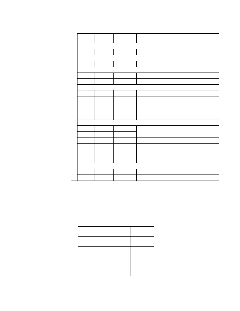
The start of active video can be set to the Active Picture lines listed in
Lock Source (Frame Sync Submodule option must be present to be active)
Second Bank - 2ND
LED
On
0
Video Input
Reference
Select Lock Source.
Picture Position Offset
1
Advance
Delay
Adjust horizontal Picture Position Offset.
H and V Delay Adjustments (Active when Frame Sync Submodule option is present)
2
Advance
Delay
Adjust Horizontal delay.
3
Advance
Delay
Adjust Vertical delay.
Freeze Configuration (Frame Sync Submodule option must be present to be active)
4
Manual
Auto
Set Freeze Recognition type.
5
Off On
Perform manual freeze.
6
Frame
Field
Select Freeze Mode.
7
Field 1
Field 2
Select Freeze Field.
8
Last Field
Black
Select Freeze Signal.
VBI.Data Line Processing
9
SAV4
SAV3
Select line number of Active Picture Start (SAV). See
the corresponding values for these controls.
A
SAV2 SAV1
B
–
–
Not used
C
Notch
Decode
Delete
Set type of processing for VBI Data Lines.
D
Setup No
Setup
Active when Notch Decode is enabled above. Select Yes if setup
is present on data lines.
SuperBlack
E
Enable Disable
(525
only)
Enable or Disable (clip) Super Black.
F
–
–
Not used
1
Grass Valley no longer supports PAL-M in any of its modular products. Although this setting may work in certain applications,
Grass Valley will not warrant that it works or provide support if problems are encountered using this product with PAL-M signals.
This product has not been modified to eliminate support for PAL-M. If this product has been used with PAL-M in the past without
problems, there shouldn’t be any issues using it for the same application. However, it is not recommended that customers use it in
any new PAL-M applications.
Table 6. 8960DEC VBI Settings
Active Picture
Start
525
625
SAV1
21 (Field 1)
284 (Field 2)
24 (Field 1)
337 (Field 2)
SAV2
22 (Field 1)
285 (Field 2)
25 (Field 1)
338 (Field 2)
SAV3
23 (Field 1)
286 (Field 2)
26 (Field 1)
339 (Field 2)
SAV4
24 (Field 1)
287 (Field 2)
27 (Field 1)
340 (Field 2)
Table 5. Decoder Configuration Functions - (continued)
Function
Switch
Paddle
Switch Up
Paddle
Switch Down
Function Description