Rear connectors, Power connection, Analog audio input – Ensemble Designs BrightEye 33 Analog Audio Distribution Amplifier User Manual
Page 4: Analog audio outputs
www.ensembledesigns.com
BrightEye 33 - Page 4
Analog Audio Distribution Amplifier User Guide
TM
BrightEye 33
REAR CONNECTORS
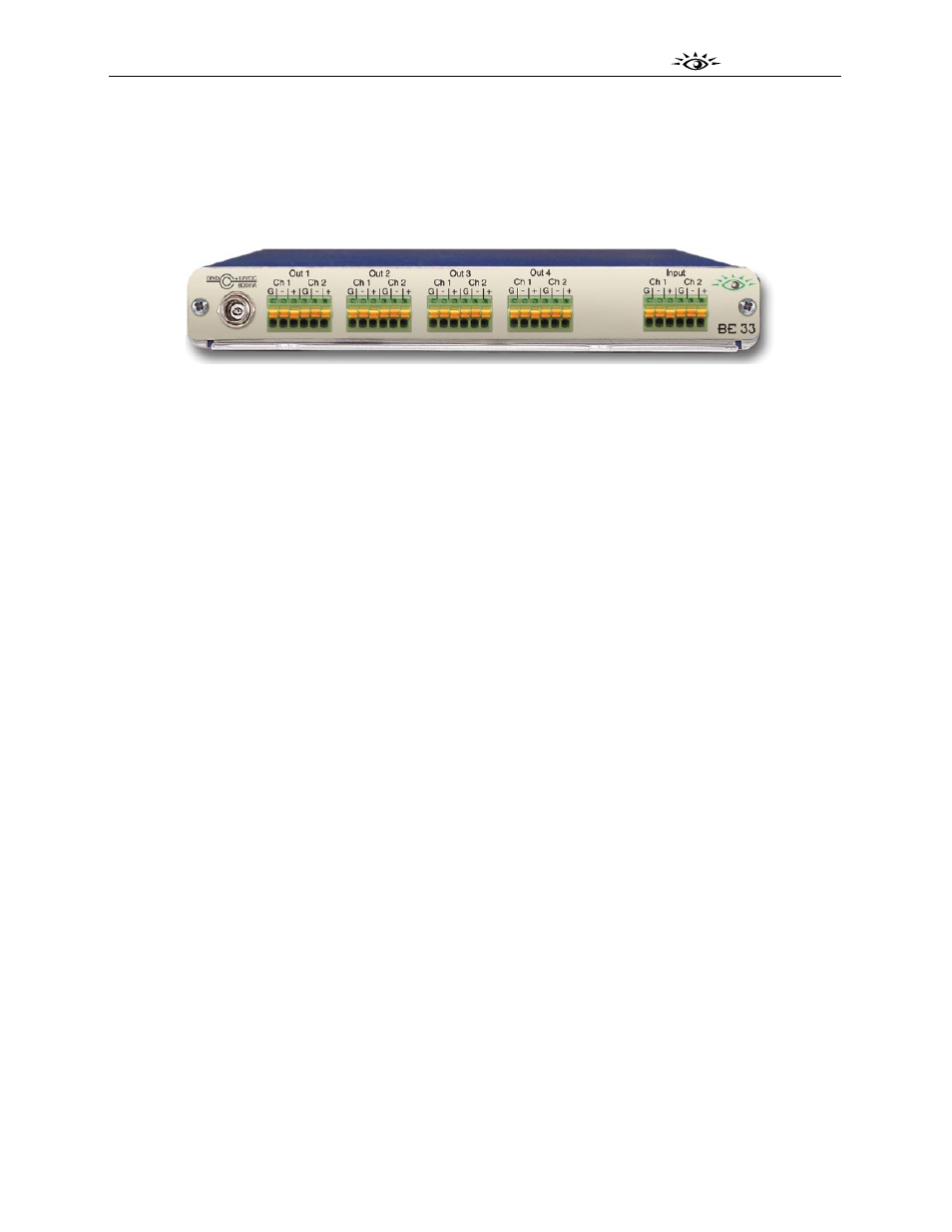
All connections to the BrightEye 33 are made on the rear of the unit. Refer to the illustration below.
BrightEye 33 Rear Connectors
Power Connection
Connect a modular power supply to the 12 volt DC power input connection on the far left of the unit.
Use the locking ring to secure it.
Analog Audio Input
This 6-pin Phoenix connector provides two channels of analog audio input. This connector is fitted
with a pluggable terminal block that accepts bare wire leads. Wires can be inserted into the small
round holes. Strip the audio wire to about 3/8” (8 mm). Solder tinning is not required. To remove the
wire, push in the pin above the connection with a small pointed tool. This will release the wire from the
connector.
Follow the legend to connect the Ground (G), Positive (+), and Negative (-) connections for each signal.
Ch 1 corresponds to the left channel in a stereo system, and Ch 2 corresponds to the right channel.
Analog Audio Outputs
The four Analog Audio Outputs provide 8 Mono Outputs or 4 Stereo Outputs of Analog Audio.
Each Audio Out connector provides two channels of balanced analog audio (1 pair). These connectors
are each fitted with a pluggable terminal block that accepts bare wire leads. Wires can be inserted into
the small round holes. Strip the audio wire to about 3/8” (8 mm). Solder tinning is not required. To
remove the wire, push in the pin above the connection with a small pointed tool. This will release the
wire from the connector.
Follow the legend to connect the Ground (G), Positive (+), and Negative (-) connections for each signal.
Ch 1 corresponds to the left channel in a stereo system, and Ch 2 corresponds to the right channel.
If connecting to an unbalanced (single-ended) destination, such as a consumer speaker amplifier, with
shielded coaxial style audio cable, connect the center conductor to the Positive (+) terminal. Then
connect the outer conductor to both the Ground (G) and Negative (-) terminals.