6600 frame frame description, Power supplies, Frame installation – Ensemble Designs 6600 Series Analog Audio DAs and Frame Models 6601, 6601R and Frame 6600 User Manual
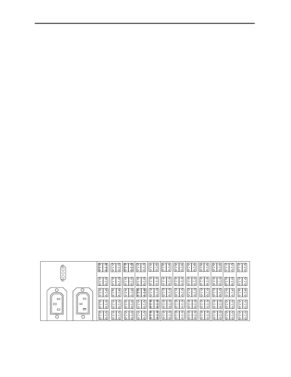
Page 4: Frame rear view – 3-pin terminal wiring
6600 FRAME
Frame Description
The Avenue 6600 2 RU rack mountable audio frame is capable of housing up to twelve
6601/6601R analog audio distribution modules. Input and output signal connections and
remote gain controls are provided with removable clamp-type barrier connectors.
Power Supplies
The frame provides mounting space for up to two PS66 power supplies for providing DC
power to the frame. The supply is auto-sensing and will operate from any input voltage in
the range 90 to 260 VAC with a frequency of 50 or 60 Hz. The supply provides ± 21V @ 40
Watts. If the power required by the frame exceeds 30 Watts, it is recommended that two
supplies be used to improve heat dissipation and reliability.
Two supplies powered from separate AC sources are always recommended to maximize
reliability. The actual power drawn from the AC supply will depend on how many ampli-
fiers and of what type are in the frame. It may be necessary to use dual supplies if the
frame is fully loaded with higher current options (see each amplifier section of this
manual).
A 3-pin Molex connector is provided on the rear of the frame. It is connected to the plus
and minus output DC rails of the power supply and can be wired to another 6600 frame.
This will provide power redundancy for the second frame without the need to purchase a
redundant supply for that frame.
Frame Installation
The Avenue 6600 frame requires 2 RU of space (3.5 in.) and is intended to be mounted in
a standard 19 in. rack. The horizontal depth required in the rack is 12.5 in. and additional
space behind the frame should be planned for audio wiring. No special cooling require-
ments are necessary, but it is desirable to avoid mounting the frame adjacent to high-
speed digital units to avoid possible noise problems.
The frame input and output connections are similar for the 6601/6601R audio modules.
The typical installation consists of groups of three-pin terminal blocks as illustrated in the
frame rear view below. Refer also to the appropriate amplifier section of this manual for
the actual frame inter-connections.
Model 6600 Analog Audio DAs and Frame
6600-4
A
12
B
A
11
B
A
10
B
A
9
B
A
8
B
A
7
B
A
6
B
A
5
B
A
4
B
A
3
B
A
2
B
A
1
B
PS–1
PS–2
+ 21V
– 21V
Frame Rear View – 3-pin Terminal Wiring