Installation, Cabling – Ensemble Designs 5140 Analog EQ DA User Manual
Page 5
Model 5140 Analog EQ Video DA
5140-5
INSTALLATION
Plug the 5140 module into any one of the slots in the 1 RU or 3 RU frames and install the
plastic overlay provided onto the corresponding group of rear BNC connectors associated
with the module location. Note that the plastic overlay has an optional adhesive backing
for securing it to the frame. Use of the adhesive backing is only necessary if you would
like the location to be permanent and is not recommended if you need to change module
locations. This module may be hot-swapped (inserted or removed) without powering down
or disturbing performance of the other modules in the system.
CABLING
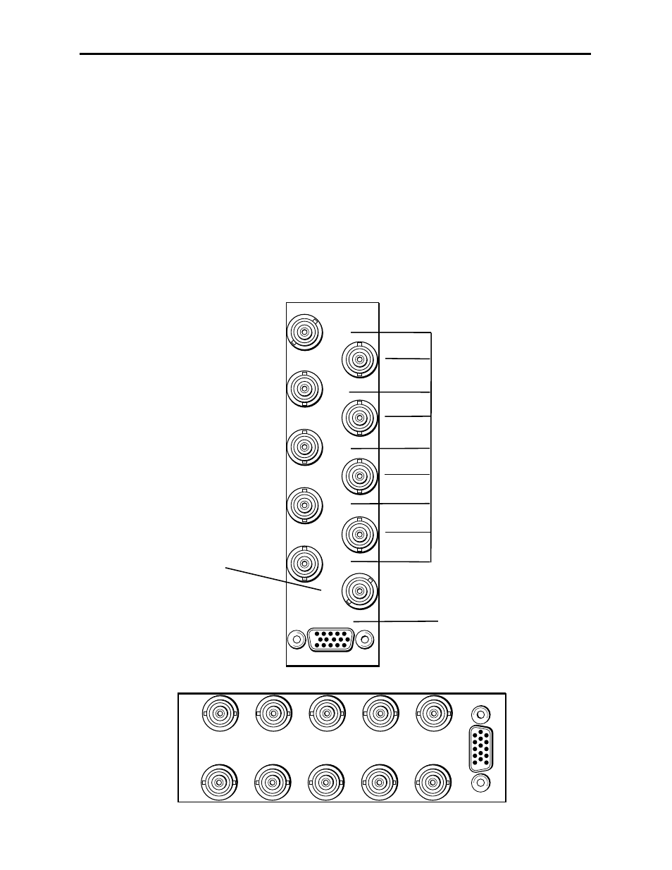
Refer to the 3 RU and 1 RU backplane diagrams of the module below for cabling instruc-
tions. Note that unless stated otherwise, the 1 RU cabling explanations are identical to
those given in the 3 RU diagram.
Out 2
Out 4
Out 6
Out 8
Input
Out 9
Out 7
Out 5
Out 3
Out 1
5140 EQ DA
Connect the analog video
source signal to be distributed
into the Input BNC.
NOTE: This input is self-ter-
minated on the module, if the
module is removed, the input
will become unterminated.
Connect up to nine
analog output destinations
to the Out 1-9 BNCs.
The 15-pin connector is not
used in this application.
3 RU Backplane
1 RU Backplane
Input
Input
Out 1
Out 2
Out 3
Out 4
Out 5
Out 6
Out 7
Out 8
Out 9
5140 EQ D
A