Dvfs28n-2 – Archgard 45-DVFS28N-2 User Manual
Page 20
45-DVFS28N-2
20
VENTING - HORIZONTALLY USING SIMPSON DURA-VENT DIRECT VENT SYSTEMS
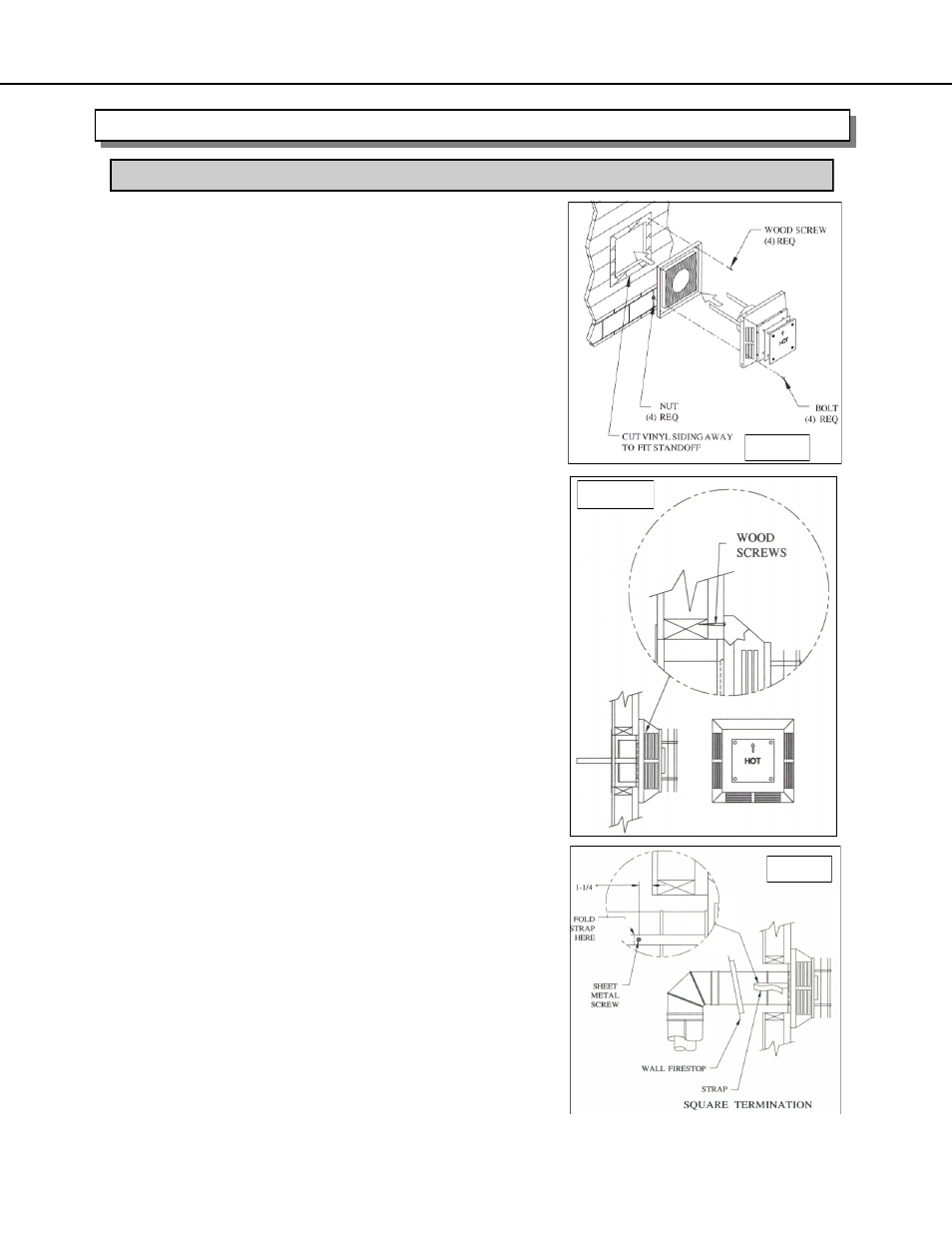
INSTALLATION PROCEDURES FOR SIMPSON DURA-VENT DIRECT VENT SYSTEM
Fig. 1
Fig. 2
Fig. 3
5. Mark the wall with an 11” (279 mm) x 10” (254 mm) hole.
See termination framing on page 22. The center of the hole
should line up with the centerline of the horizontal pipe. Cut
and frame the 11” (279 mm) x 10” (254 mm) hole in the
exterior wall where the vent will be terminated. If the wall
being penetrated is constructed of non-combustible
material, (I.E. a masonry block, or concrete) a hole with
zero clearance is acceptable. NOTE: The horizontal run of
vent must be level, or have a ¼” (6 mm) rise for every
12” (305 mm) of run towards the termination. Never allow
the vent to run downward. This could cause high
temperatures and may present the possibility of a fire.
ALSO: The location of the horizontal vent termination on an
exterior wall must meet local and national building codes,
and must not be blocked or obstructed. For Allowable
Termination Locations see page 11 in this manual.
6. Position the Horizontal Vent Termination in the center of the
square hole (arrow on the vent cap should be facing UP),
and run a bead of non-hardening sealant around the outside
edges of the termination, so as to make a seal between the
termination and the wall. Finish attaching the termination
cap to the wall with the four wood screws provided with the
termination cap. NOTE: The four wood screws provided
should be replaced with the appropriate fasteners for
stucco, brick, concrete or other types of siding. For buildings
with VINYL SIDING, a Vinyl Siding Standoff should be
installed between the vent cap and the exterior wall. Attach
the Vinyl Siding Standoff to the Horizontal Termination Cap
by bolting the flat portion of the Vinyl Siding Standoff (Fig.1)
so that an air space will exist between the wall and the Vent
Termination.
7. Locate and slide the Wall Thimble Cover over the vent pipe.
8. Slide the appliance and vent assembly towards the wall,
carefully inserting the vent pipe into the vent cap assembly.
It is important that the vent pipe extend into the vent cap
sufficient distance so as to result in a minimum pipe overlap
of 1 ¼” (31 mm). Secure the connection between the vent
pipe and the vent cap by attaching the two sheet metal
strips extending from the vent cap assembly into the outer
all of the vent pipe. Use the two sheet metal screws
provided to connect the strips to the pipe section. Bend any
remaining portion of the sheet metal strip back towards the
vent cap, so it will be concealed by the Wall Thimble Cover.
(Fig. 2)
9. Slide the Wall Thimble Cover up to the wall surface and
attach to the wall with wood screws. (Fig. 3)