Power unit assembly, Fig. 30 – AIRLESSCO SS4550 User Manual
Page 28
26
27
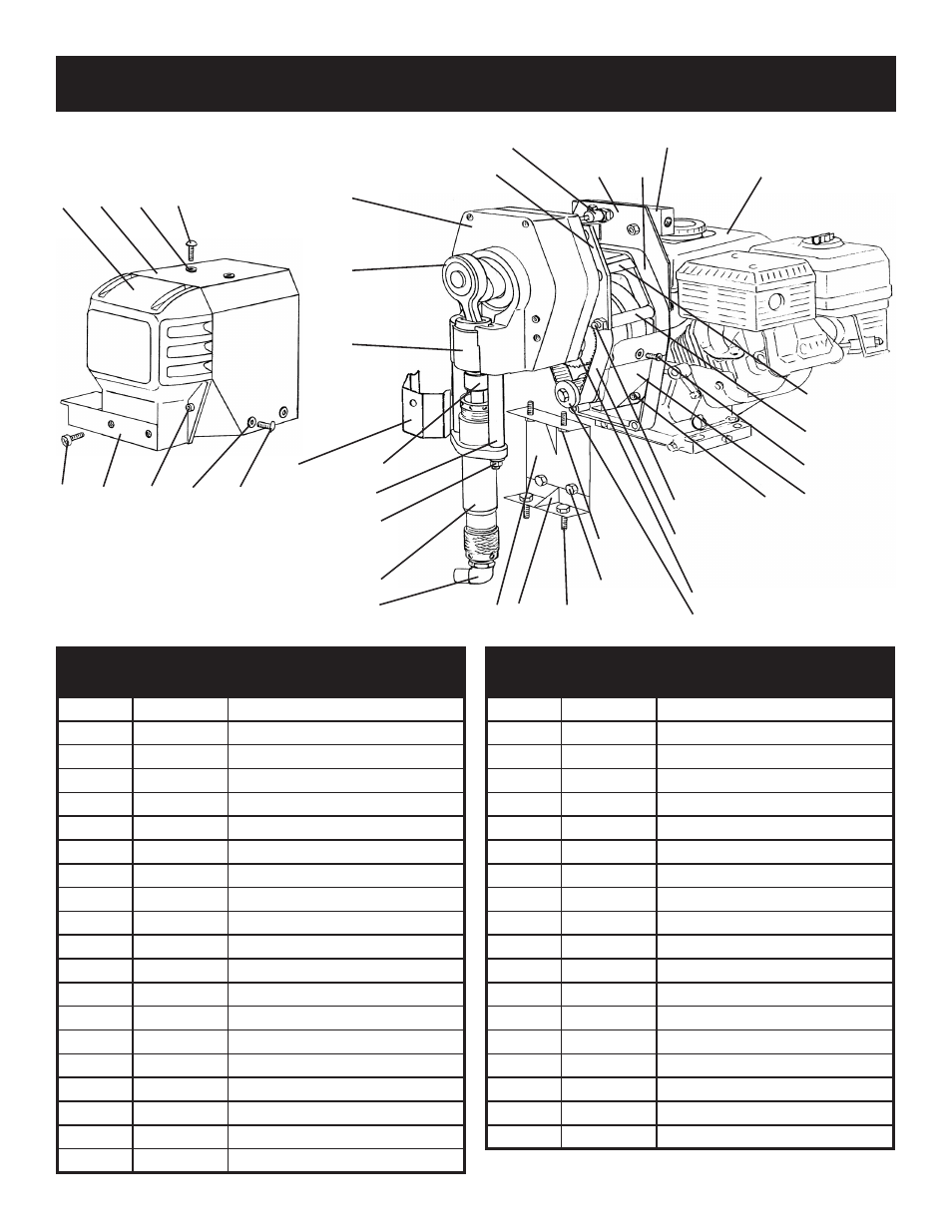
POWER UNIT ASSEMBLY
FIG. 30
1
PARTS LIST FIGURE 30
Item No.
Part No.
Description
1
301-320
Gearbox Cover
2
301-531
Top Cover
3
301-135
Grommet (6)
4
301-337
Screw (2)
5
301-047
Sleeve Bearing
6
301-333
Connection Rod
7
301-208
Gearbox
8
305-045
Gearbox Mounting Plate
9
305-064
Manifold Holder
10
305-012
Adapter
11
301-160
Honda GX160 Engine
12
301-529
Splash Cover
13
305-046
Tube Spacer (4)
14
136-091
Screw (2)
15
305-067
Bottom Cover
16
100-345
Screw (2)
17
305-047
Stud (4)
18
140-044
Nut (8)
19
301-231
Cog Belt
20
111-044
Screw (4)
PARTS LIST FIGURE 30 CONT
Item No.
Part No.
Description
21
140-029
Washer (10)
22
113-023
Washer (4)
23
100-317
Nut (4)
24
169-050
Screw (2)
25
301-299
Bottom Support
26
301-232
Top Support
27
100-328
Stud (2)
28
140-035
Washer (2)
29
140-051
Nut (2)
30
301-059
Spacer (2)
31
189-047
Coupling Set Cover
32
189-046
Coupling Set
33
189-048
Retainign Rings
34
301-467
Shield
35
111-037
Screw (4)
36
100-312
Screw (4)
37
305-140
Manifold Filter Bracket
38
100-360
Screw (2)
*
188-160
Grounding Assy
FIGURE 26
FIGURE 23
FIGURE 27
FIGURE 30
FIGURE 22
FIGURE 40
2
3
4
5
6
7
8
9
10
11
12
13
14
15
16
17, 18
19
25
26
30
34
35
3
36
37
38
20, 21
20, 21, 22, 23
21, 22, 23, 24
27, 28, 29
31, 32, 33