Servicing the outlet valve, Servicing the inlet assembly, Fig. 14 fig. 13 – AIRLESSCO SS3650 User Manual
Page 17
14
15
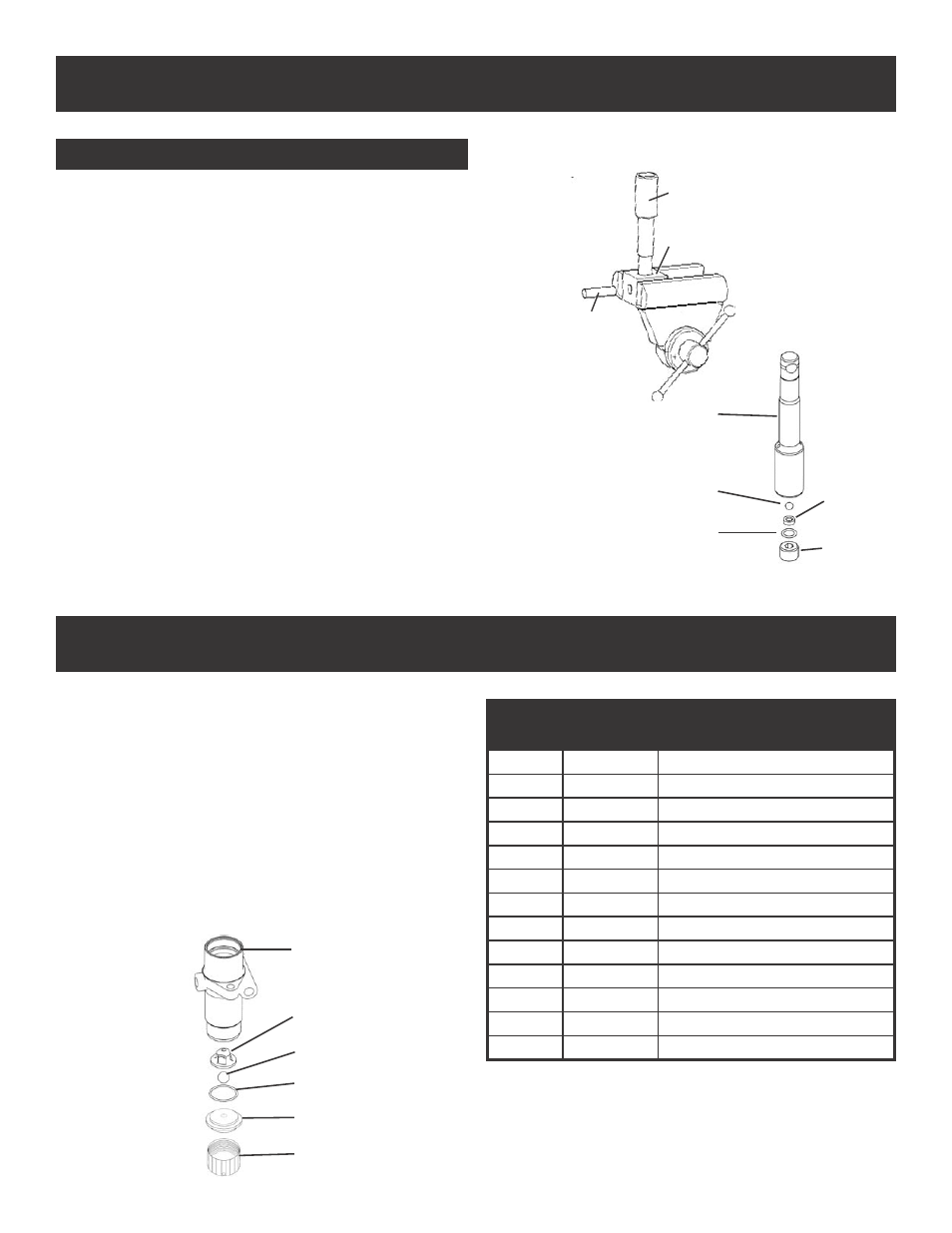
SERVICING THE OUTLET VALVE
9
10
11
12
8
13
1. Disconnect the Fluid Pump following instructions on
page 14.
2. Place piston holder in a vise. Slide piston into the holder
& lock in place with a 3/8” dowel.
3. Use a 1/4” allen wrench to unscrew the outlet seat
retainer from the piston.
4. Remove the outlet seat, O-ring and outlet ball.
5. Inspect outlet ball & seat for wear. Replace as
necessary. Ensure seat is right side up.
6. While piston is still locked in the holder, install parts back
into the piston in the following order:
BALL, OUTLET SEAT AND O-RING
Before reinstalling the outlet seat support, apply two
drops of Loctite No. 242 (blue) on the threads & torque to
20 ft-lbs.
NOTE: Airlessco LP pump tool kit 188-197 is required
for this task. Kit includes: Tightening Bar (189-211),
Packing Removal Tool (331-465), Piston Holder (331-
195), 3/8” dowel (331-196).
SERVICING THE INLET ASSEMBLY
1. Un-thread and remove suction nut from the fluid pump
body.
2. Remove suction seat, O-ring, suction ball and suction
retainer.
3. Clean all parts and inspect them for wear or damage,
replacing parts as needed.
4. Clean inside of the fluid pump body.
5. Reassemble lower suction valve assembly by placing the
suction seat, O-ring, suction ball & suction ball guide in
the suction nut & screw onto fluid pump body.
DISASSEMBLY OF THE OUTLET VALVE
FIG. 14
FIG. 13
PARTS LIST FIGURE 13 & 14
Item No.
Part No.
Description
1
331-708
Piston
2
331-195
Piston Holder
3
331-196
Dowel Pin
4
331-027
Outlet Ball
5
331-100
O-Ring
6
331-026
Outlet Seat
7
331-314
Outlet Seat Retainer
8
331-011
Fluid Pump Body
9
331-029
Suction Ball Guide
10
331-030
Suction Ball
11
106-011
O-Ring
12
331-409
Suction Seat
13
331-034
Suction Nut
1
2
3
1
4
5
6
7