Servicing the fluid pump, Fig. 12 – AIRLESSCO SS3650 User Manual
Page 16
14
15
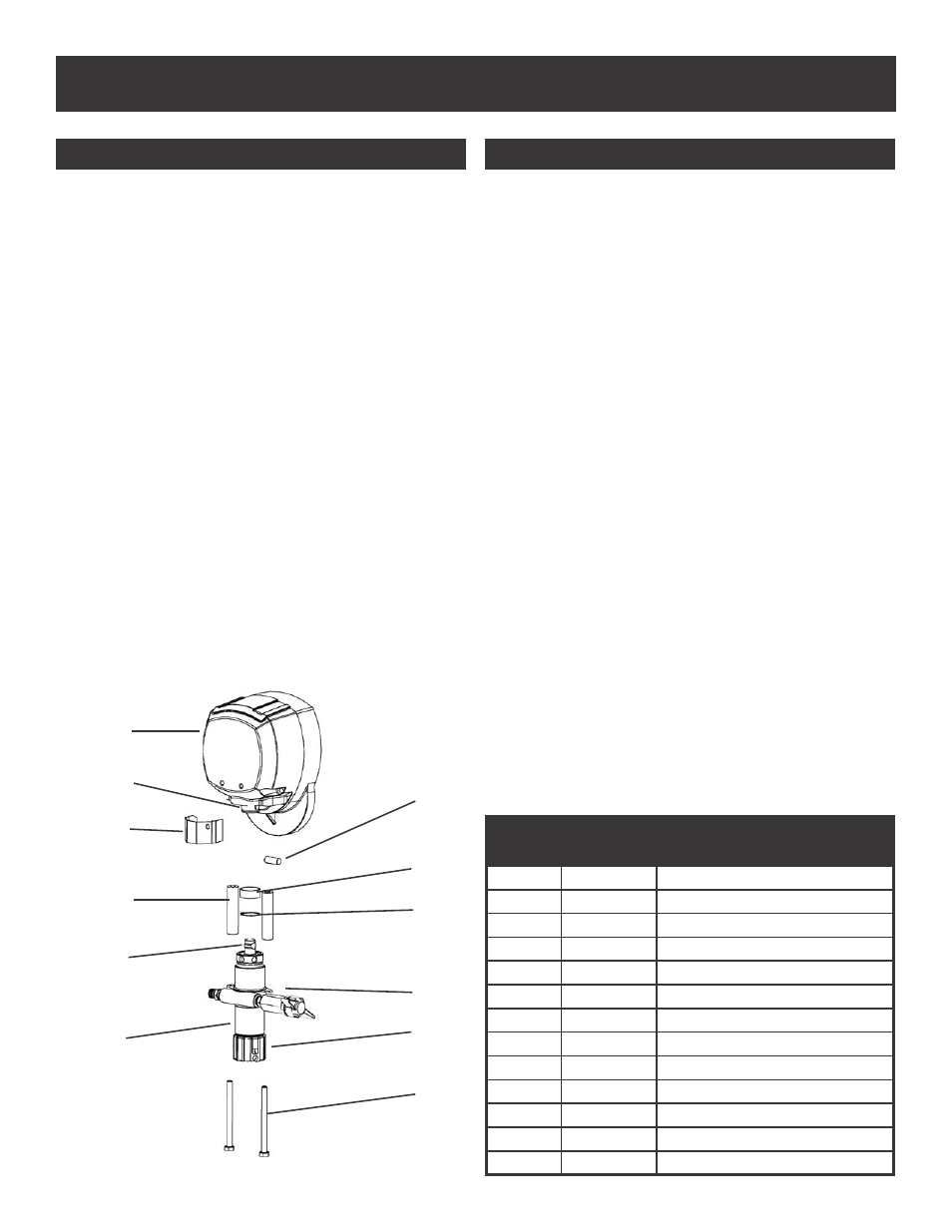
SERVICING THE FLUID PUMP
REFER TO FIGURE 12
1. Follow the Pressure Relief Procedure on page 8.
2. Flush the material you are spraying out of the
machine.
3. Remove the connecting rod shield.
4. Move the piston rod to its lowest position by
cycling pump slowly.
5. Turn off the motor.
6. Disconnect sensor by holding it in place with a 7/8”
wrench and unscrewing the swivel with a 11/16”
wrench.
7. Remove the retaining ring from the connecting rod
and slide the sleeve down revealing the connecting
rod pin.
8. Remove the suction tube assembly from the fluid
pump by unscrewing the suction nut with the packing
adjustment tool (189-211).
9. Using a 1/2” wrench unscrew the two bolts from
the cover assembly. The fluid pump will be hanging
loosely at this point.
10.Remove the connecting rod pin out of the
connecting rod, allowing the removal of the fluid
pump from the machine.
REFER TO FIGURES 12 & 14
1. Loosen the packing nut and ensure that the piston rod
is in its upper position in the fluid pump body. Slip the
sleeve & the retaining ring over the piston rod.
2. Push the piston rod up into the connecting rod & align
the holes. Insert the connecting rod pin through the
connecting rod & piston. Slip the sleeve up over the
connecting rod pin and insert the retaining ring into the
groove on the connecting rod.
3. Push the two bolts through the tube spacers & screw
them into the cover assembly. Using a 1/2” wrench,
tighten the two bolts evenly (alternating between them)
until you reach 20 ft-lbs.
4. Reassemble lower suction valve assembly by placing
the suction seat, O-ring, suction ball & suction ball guide
in the suction nut & screw onto fluid pump body.
5. Reconnect sensor to the fluid pump body. Hold sensor
with a 7/8” wrench while tightening the swivel with a
11/16” wrench.
6. Start the machine and operate slowly to check the piston
rod for binding. Adjust the two bolts, holding the fluid
pump body to the cover assembly, if necessary. This will
eliminate any binding.
7. Tighten packing nut clockwise until resistance is felt
against the Belleville Springs, go 3/4 of a turn more. Put
five drops of Airlessco Throat Seal Oil in the packing nut.
8. Run the machine at full pressure for several minutes.
Release the pressure by following the Pressure Relief
Procedure & readjust the packing nut per step 7 above.
9. Install the connecting rod shield so that the
small hole is in the upper right hand corner.
FLUID PUMP DISCONNECT
FLUID PUMP REINSTALL
1
2
3
8
9
4,5
7
6
10
11
12
13
PARTS LIST FIGURE 12
Item No.
Part No.
Description
1
119-028
Connecting Rod Pin
2
331-117
Sleeve
3
331-062
Retaining Ring
4
115-019
Hose Connector
5
100-603
Swivel
6
331-034
Suction Nut
7
100-318
Bolts
8
331-209
Fluid Pump
9
331-093
Piston Rod
10
331-074
Tube Spacers
11
331-111
Connection Rod Shield
12
331-038
Connecting Rod
13
331-537
Cover Assembly
FIG. 12